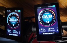
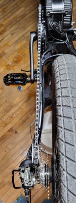
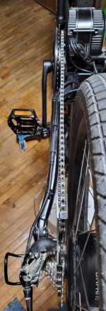
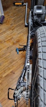
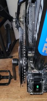
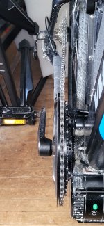
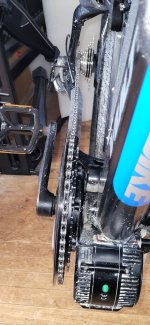
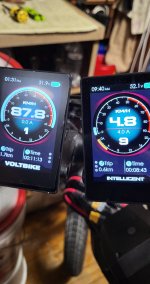
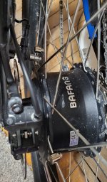
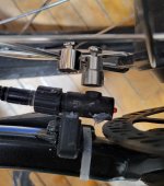
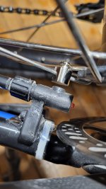
I finally took my ebike for a test ride.

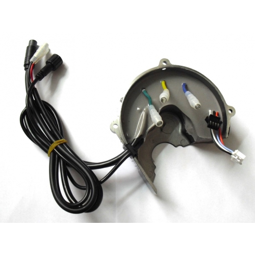
I need to do a splice. I need to take out a female connector from a controller to a motor and replace it. I will show it when I do it. I am putting it off today due to a really good new dystopian Si-Fi novel. "The Felicity Complex." I just want to read it. I made a bunch of cash today anyway. When I splice, I cut cleanly with an extra 20mm of overlap. The wires get fanned and soldered. 2mm heatshrink goes over each. Then half go one way and half the other and larger marine shrinktube goes over the entire thing. I only stagger slightly inside battery mounts. This book will become a sanitized movie in a few years with all the good parts edited out, like the girl on girl scenes in the closet. @PCeBiker has very nice tires.

1785625964949.png
 
Last edited:
When I splice, I cut cleanly with an extra 20mm of overlap. The wires get fanned and soldered.

I had to add quite a bit of length, so that gave me room to stagger each splice.
I cut the wires exactly to length with ~10 mm overlap of each wire that got stripped off, then the wires were twisted together and soldered.


2mm heatshrink goes over each.

I didn't need the 2mm heat shrink because my splices are far enough apart that they don't touch each other when folded over.

It helps to keep the outer shrink tube from getting all lumpy, and it's easier to feed through the outer shrink tube.


larger marine shrinktube goes over the entire thing.

I used double walled heat shrink tube with glue but only heated and sealed the ends where it overlapped the original cable.

I only shrunk the overlapping ends so my cable looks a little neater, and I can open it up easily if I need to, because the middle isn't glued.


@PCeBiker has very nice tires.


I bought a pair of Schwalbe Super Moto-X tires the day after I bought a Schwalbe Hurricane tire.


I mistakingly thought that my Super Moto-X tires were only bicycle rated, but they have MOPED printed on them near the wire tire bead,..


.
 

Attachments

  • 20260801_212351.jpg
    20260801_212351.jpg
    333.5 KB · Views: 22
  • 20240316_135003.jpg
    20240316_135003.jpg
    301.7 KB · Views: 20
  • 20240316_135432.jpg
    20240316_135432.jpg
    254.2 KB · Views: 20
Last edited:
Those tires fly. I am stuck working on mostly sucky bikes. Next is another Ape-Ass, Aipas bike. I swapped the grips and gave it a push-in throttle. Then it got PickUp e50 cargo tires and a Bontrager saddle. Today it is getting quad hydros over the single pad movement cable brakes. Oh, and I ditched the plastic pedals. He wants to commute so flats are not an option, so it also has FlatOut.

1785642816551.png


1785697561834.jpeg
 
Last edited:
1785697561834.jpeg


I don't cut my cable like that.

I slice the outer cable casing open and remove as much as possible (leaving an inch or so remaining for the shrink tube overlap at each end).

So in your photo, I would have removed about 4-5 inches of the outer cable insulation exposing the fully intact 9 wires inside.

That would give me enough room to stagger maybe all of connections enough to not need internal shrink tube, or at least I wouldn't have one Big Lump of connections to have to stash somewhere.
 
EDIT:
You've got plenty of room to peel back the casing to stagger you're connections,..

1785697561834.jpeg


As long as this isn't what you're going to splice into??

1785697561834.jpg


That's too short to stagger.
 
There often isn't enough length to stagger the individual wire splices.
Even when there is, I personally don't like the look of a long "lumpy" piece of shrink tubing in the wire run.
The connector itself is a large "bump" in the run, I prefer to make the splice the same size with a shorter piece of shrink.
To improve the look, I use micro spiral wrap to make the wire run look more consistent.
In some cases, where stress isn't a problem, you can just put waterproof shrink on the individual wire solder joints and not cover the entire cable with a larger piece. The micro spiral wrap provides the necessary protection.
 
I admit that that splice was a pain. I started early and the light was not good. Little wires got accidently mixed by large fingers. I was left with one pair to match, a little black wire and a little green wire. When twisting wires an adjacent one got mixed in. I had to wait until noon and get it into the light to sort it out. It is a brand new motor. It all tested great in the stand. The kid picked it up. It went 175 meters and the motor locked up. I took off the brake and the wheel will not turn regardless of the amount of force applied.
 
Now I am attempting to get a hydro line through a frame. It is such a PITA. There are four other lines in there between the battery compartment and the upper part of the down tube. It cannot cross any of them or it will not fit. I can get a cable through to fish it but it keeps crossing another line, then jams.
 
Now I am attempting to get a hydro line through a frame. It is such a PITA. There are four other lines in there between the battery compartment and the upper part of the down tube. It cannot cross any of them or it will not fit. I can get a cable through to fish it but it keeps crossing another line, then jams.
Pull what's in back down and then pull them all in together.
Stagger the forward ends so the head is not one big nut.
 
So, I had to chop off the olive and nut. I got it through. But it is too short! It will take a whole new hose and a full bleed. What to do when your hose it too short?
 
Sounds like the carpenter who cut a piece of wood 3 times... and it was still too short 🙃
I know Tektro makes line couplings for longer installs... like on a tandem. But I'd probably just replace it.
 
It was pre-bleed kit. I am getting 3 meters. The front is easy. The guy with the custom Ti bike is sending in his boss for a conversion. That is so much better than these Amazon bikes and MacFoxes. I need to take the bad with the good.
 
I just encountered a first for me. On new, just out of the box, single-speed freewheel hub-drives, stand and jump on the pedals before ever using the throttle. Otherwise the freewheel can unscrew, press against the dropout and zeize. It happened right in front of me. Don't count on the factory torquing it. Or, someone could die.
 
Google said this:
What Drives PedalUma's 5.0 Google Standing?
  • By-Appointment Workshop Model: Unlike chaotic walk-in retail shops, they work exclusively by appointment. Clients meet at an unhurried, private central lobby conference table to map out their build or diagnostic needs face-to-face with the builder. [1]
  • Ultra-Stealth Custom Systems: They build high-performance electric systems that routinely outperform mass-market retail options. Their specialty is creating customized e-bikes that beautifully hide the motorized elements, so the finished build looks exactly like a traditional bike. [1]
  • No-Pressure Service Mentality: Reviewers frequently call out the shop's technical integrity—often solving obscure troubleshooting bugs for community riders online for free, or pointing clients toward manufacturer warranty options instead of forcing unnecessary part replacements. [1]
 
Another thought is to set the throttle to By Displays Command. This will give you 9 different maximum throttle outputs (matching PAS) and you can just hold it wide open instead of trying to vary rotation.

I ended up doing exactly that.

At first I thought it would be easier to just have 3 different maximum throttle outputs, and make 4-9 PAS settings at max,..


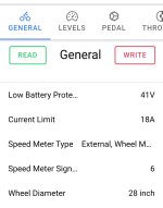
Screenshot_20260804_101310_Speeed.jpg


Screenshot_20260804_101321_Speeed.jpg


It worked but it struggled to hold a steady 32 kph and the power would surge from 1 amp to 18 amps to try and maintain a constant speed.
I would turn down the throttle a bit, and the next throttle setting appeared to be ~13.5 amps, and then 7 or 8 amps, so not as granular as I'd like.


So I redid my settings to what @Gionnirocket said but set all the maximum speeds (except the first few) to 32 kph.


Screenshot_20260805_094109_Speeed.jpg


Screenshot_20260805_094131_Speeed.jpg


That worked great.
The surging was limited to the PAS mode setting, and after the first couple of tries at maintaining the 32 kph speed setting, the controller wouldn't back the power off as much.

So I would just keep hitting the PAS up button until I got up to 32 kph.
Then if I started to slow down (more wind or whatever) I'd hit the up button again.
If it started surging again, I'd just hit the down button.

It was kinda windy, so the current draw was bouncing around between 3 and 18 amps, so I did need to use the PAS buttons a lot, but if the PAS setting was close to the amps needed at the time, then I couldn't feel and surging.


And the rest of my settings,..


.
 

Attachments

  • Screenshot_20260805_094145_Speeed.jpg
    Screenshot_20260805_094145_Speeed.jpg
    102.9 KB · Views: 11
  • Screenshot_20260805_094157_Speeed.jpg
    Screenshot_20260805_094157_Speeed.jpg
    147.5 KB · Views: 10
So,..
I figure that my single speed magnet is causing the surging.
There's only one pulse per revolution.


20260731_200216.jpg


So I bought more speed magnets to increase my revolutionary resolution,..


Screenshot_20260808_060402_AliExpress.jpg


I've got a 36 spoke wheel with 18 spokes on each side of the hub, with 9 of those spokes going the same direction.

I figure it's important to have the magnets exactly evenly spaced, so I figure 3 magnets.

My next step would be install 9 magnets, but that's a Lotta Friggen magnets !!
Maybe I'll install a second hal sensor in my hub motor to monitor the six speed magnets.

Or, I could probably monitor my hub motors speed sensor wire with some kind of circuit that I could feed into mid-drive motor?

I can't splice the wire directly into each controller, because that might short out the controllers or sensor somehow?
 
For how you want to ride I would try this....
Remove the Speed restriction on all the PAS settings by setting them all to 100% and only have an increase in current with each PAS tap up.
On the display make sure the Maximum Speed is set high or at least your upper desired limit.. 32km/h?
Post a pic of the Pedal Settings page
 
Last edited:
Here's a homework assignment if you haven't seen this yet... I agree with most of it.

Not sure how much of this affects the throttle as I rarely used mine and typically just for a few seconds... But these settings smoothed out the motor more than any other settings. I think my final Stop Decay was 130
I'd give them a try
pa.jpg
 
Back