You are using an out of date browser. It may not display this or other websites correctly.
You should upgrade or use an alternative browser.
You should upgrade or use an alternative browser.
I finally took my ebike for a test ride.
- Thread starter PCeBiker
- Start date




PCeBiker
No-Hands No-Pedaling No-Credentials
- Region
- Canada
I was out for a ride today.
The wind was gusting over 20 mph, so it was a real challenge to ride no-hands, and A Lot of Fun !!
I did some further speed, power, and gear testing on the mid-drive.
My first few PAS modes were pretty much useless, and I needed to get to PAS 5 before I any real power or speed, so I'm gunna turn up the amps a bit faster.
I'm still going to start at 1 amp though to hopefully prevent any "clacking" of my freewheel.
I've realized that I want to have my throttle always active, even in PAS 0 because I don't want to be screwing up and forgetting to put it in PAS 0
So I'm just gunna get used to checking that my throttles are both off, and always having a finger on a brake lever.
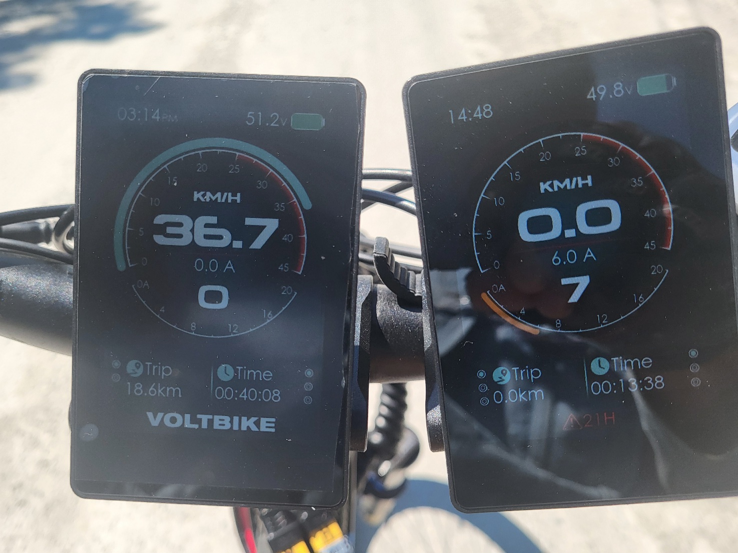
PAS 7 got me going 36.7 kph using 6.0 amps and no help from the hub-drive (except to monitor the speed).
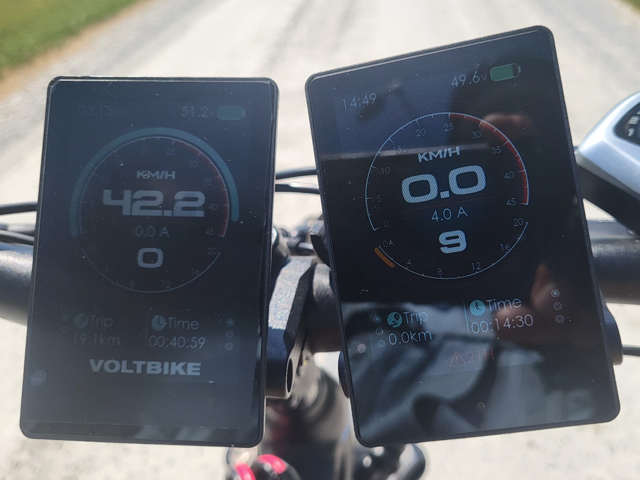
In PAS 9 with 18 amps available, I had it going 42.2 kph on the 11t rear sprocket, but it was only drawing 4.0 amps.
Then it got going 43.5 kph and the current dropped further to 2 amps,..
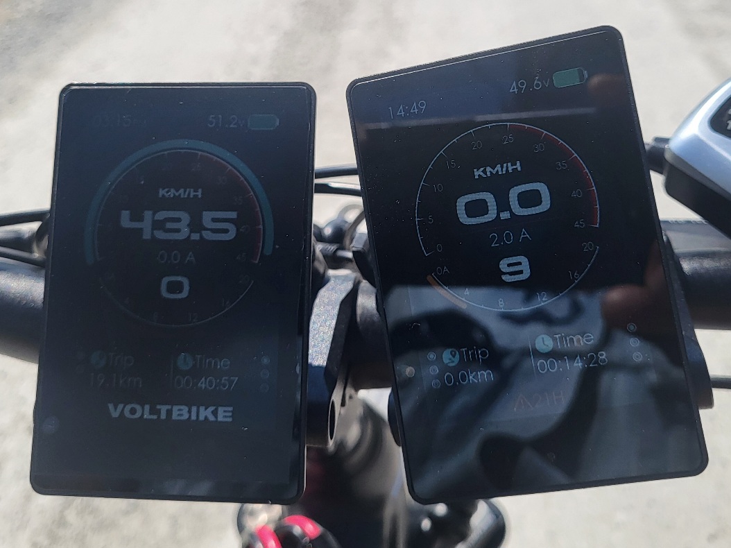
So I think I was at my maximum revolutions per volt thing, because the motor stopped drawing power?
I've decided to hook up my speed sensor and set my speed limit to 32 kph, because going 43.5 kph was Way Too Much FUN !!
And of course it took both hands and both eyes to take speedometer pictures, so there's that too.
And the 20 mph crosswinds.
The wind was gusting over 20 mph, so it was a real challenge to ride no-hands, and A Lot of Fun !!
I did some further speed, power, and gear testing on the mid-drive.
My first few PAS modes were pretty much useless, and I needed to get to PAS 5 before I any real power or speed, so I'm gunna turn up the amps a bit faster.
I'm still going to start at 1 amp though to hopefully prevent any "clacking" of my freewheel.
I've realized that I want to have my throttle always active, even in PAS 0 because I don't want to be screwing up and forgetting to put it in PAS 0
So I'm just gunna get used to checking that my throttles are both off, and always having a finger on a brake lever.
PAS 7 got me going 36.7 kph using 6.0 amps and no help from the hub-drive (except to monitor the speed).
In PAS 9 with 18 amps available, I had it going 42.2 kph on the 11t rear sprocket, but it was only drawing 4.0 amps.
Then it got going 43.5 kph and the current dropped further to 2 amps,..
So I think I was at my maximum revolutions per volt thing, because the motor stopped drawing power?
I've decided to hook up my speed sensor and set my speed limit to 32 kph, because going 43.5 kph was Way Too Much FUN !!
And of course it took both hands and both eyes to take speedometer pictures, so there's that too.
And the 20 mph crosswinds.
PCeBiker
No-Hands No-Pedaling No-Credentials
- Region
- Canada
I decided to weigh my ebike.
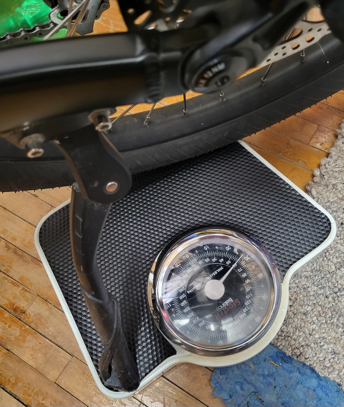
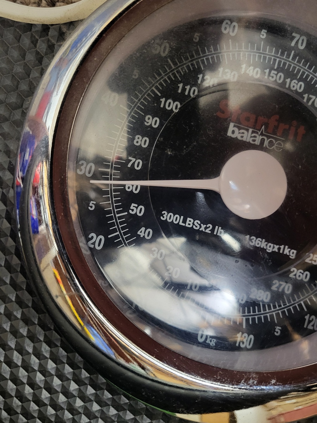
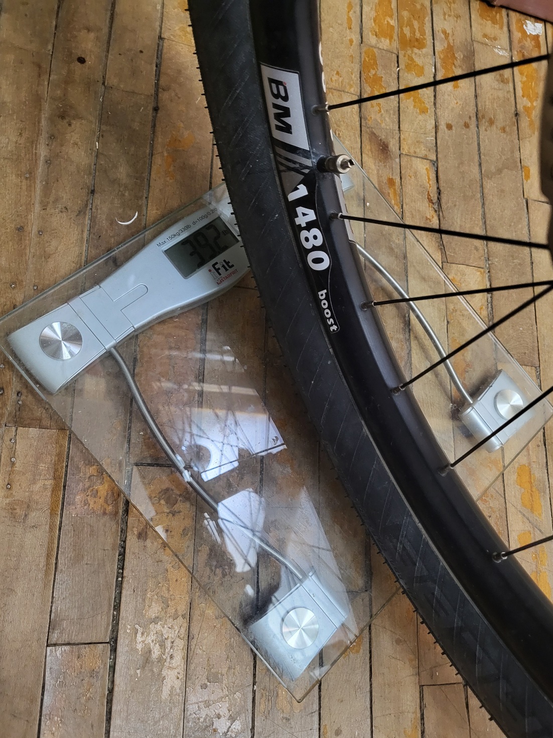
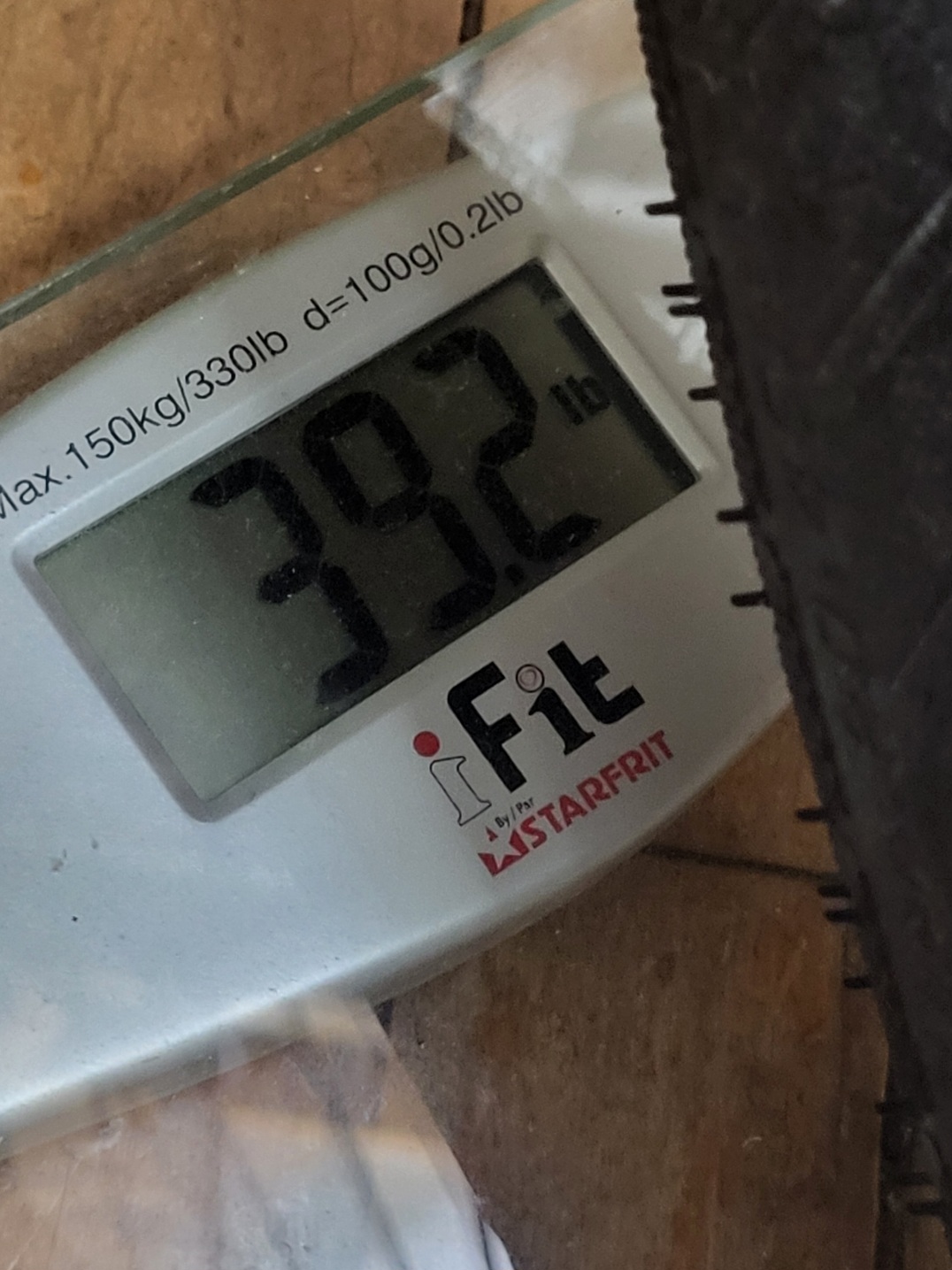
So, it looks like I've finally reached my Hundred Pound goal !!??
I always wanted to impress PedalUma and Stephan with a hundred pound ebike.
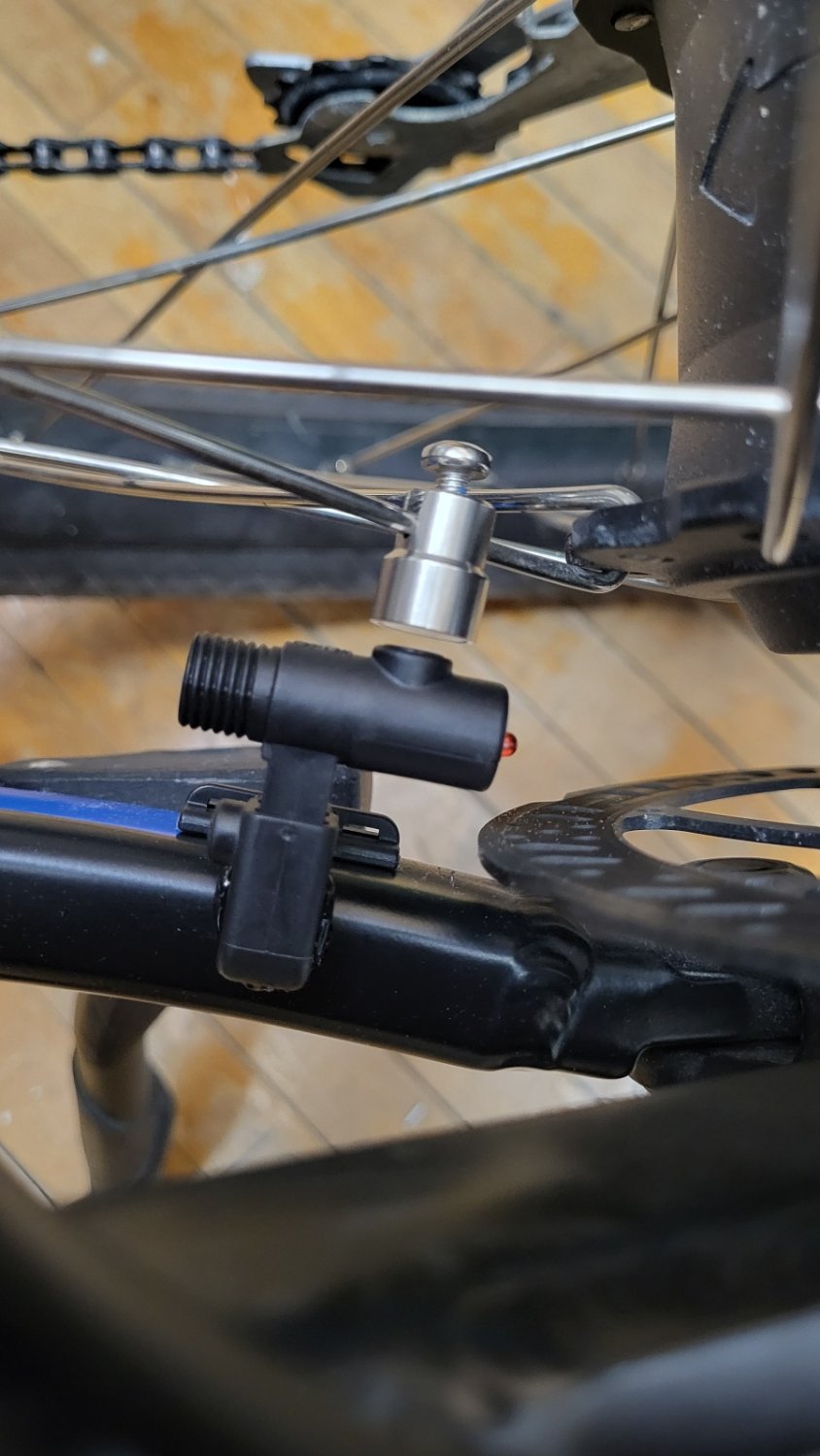
And my speed sensor is almost fully installed.
Just gotta connect the cable,..
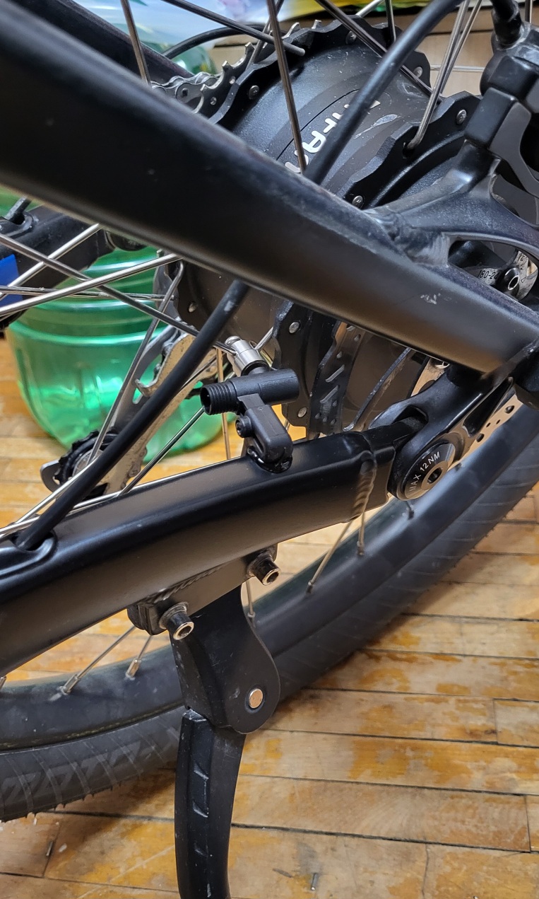
I also managed to NOT Try to use first gear during my test ride yesterday.
I'm pretty sure I'd have a Serious Problem if I tried to force the chain into first gear with the chain being too short?
So, it looks like I've finally reached my Hundred Pound goal !!??
I always wanted to impress PedalUma and Stephan with a hundred pound ebike.
And my speed sensor is almost fully installed.
Just gotta connect the cable,..
I also managed to NOT Try to use first gear during my test ride yesterday.
I'm pretty sure I'd have a Serious Problem if I tried to force the chain into first gear with the chain being too short?
Last edited:

stompandgo
Well-Known Member
- Region
- USA
My favorite brand of hub. Bulletproof, but if you need support, they are always there. They are local to you, so you can probably just stop by.



PedalUma
Well-Known Member
- Region
- USA
- City
- Petaluma, CA
The guy last week was in the shop that was building the wheels asking about how they are progressing when the owner of White Industries approached and spoke up, 'Yes those tandem hubs are ready'. He was there for a Vado update. The bike has given its owner lots of stories and connections. Since stopping riding his bike he has gained some weight. Hence the extra strong rims and hubs. Having some assistance will get him out more. It is a handmade Ti bike by Tom Kellogg, who you mentioned that you knew. It has been sitting here without wheels for three months. The wheel builder took them home to lace in peace and quiet with total focus. The shop always has too much going on.
PedalUma
Well-Known Member
- Region
- USA
- City
- Petaluma, CA
@Frank/Delaware, This is her review:

Tara Spitalnyopen_in_new
3 reviews • 0 photos
starstarstarstarstar 20 hours ago
Quick. Friendly. Fair price.


PedalUma eBikes
Tara Spitalnyopen_in_new
3 reviews • 0 photos
starstarstarstarstar 20 hours ago
Quick. Friendly. Fair price.
PedalUma eBikes
PCeBiker
No-Hands No-Pedaling No-Credentials
- Region
- Canada
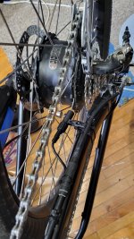
And my speed sensor is almost fully installed.
Just gotta connect the cable,..
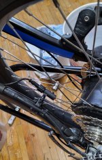
Ahh Crap !! The damn cable is too short !!
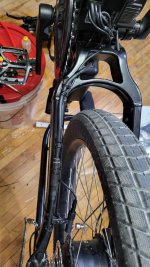
So I installed the sensor on the other side,..
Had to move the sensor and magnet further up the swingarm (or chainstay as you guys call it) to get them close enough together.
I'm still outta spec, but it is working,..
The whole thing looks like crap, and it looks Way Too percariously perched.
If I ever drop my chain, I'll probably take out the sensor?
I'm gunna try it, then probably extend the wire and swap it back to the other side.
What a PITA.
I can at least move it to the other side and further up the swingarm without extending the wire, but I liked how the sensor was tucked away nicely beside the rotor.
Attachments
Last edited:
PCeBiker
No-Hands No-Pedaling No-Credentials
- Region
- Canada
You can not over rev' an electric motor in this application...
So I think I was at my maximum revolutions per volt thing, because the motor stopped drawing power?
I did another speed test yesterday, and managed to go 49.8 kph in high gear and PAS mode 9 (and a 10 mph tailwind)
This time it was drawing the full 18 amps continuous, and power was kinda cutting in and out.
I think it's some kinda "safe mode" the motor goes into when there's no speed data?
I just spun up my wheel to full speed, and didn't get error code 21
It said I was going 0.4 kph, so it's a little out of adjustment.
PCeBiker
No-Hands No-Pedaling No-Credentials
- Region
- Canada
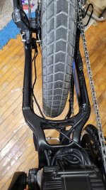
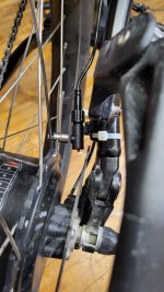
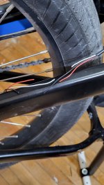
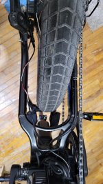
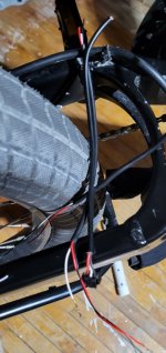
I decided to redo my speed sensor.
I'm gunna splice in a length of wire.
I staggered the cuts so I don't have to shrink tube each wire, and I won't get a big lump at the joints.
I've got some 3-wire cable from my throttle experiments.
I'm gunna splice in a length of wire.
I staggered the cuts so I don't have to shrink tube each wire, and I won't get a big lump at the joints.
I've got some 3-wire cable from my throttle experiments.
Attachments
PCeBiker
No-Hands No-Pedaling No-Credentials
- Region
- Canada
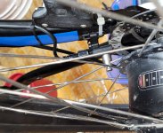
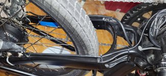
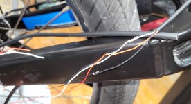
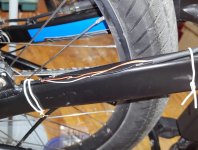
I got my speed sensor installed with the wire lengthened,..
I'm happy with it now.
I actually remembered to put the shrink tube on before soldering the wires together !!
I've been using shrink tube since the early 80's and I still forget half the time.
I'm happy with it now.
I actually remembered to put the shrink tube on before soldering the wires together !!
I've been using shrink tube since the early 80's and I still forget half the time.
Attachments
PCeBiker
No-Hands No-Pedaling No-Credentials
- Region
- Canada
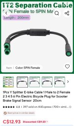
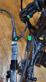
I bought a 5 pin Y-connector so I can use my display buttons with my programming cable connected.
I'm stuck in PAS 1 with just my programming cable connected.
Thanks @Gionnirocket for that idea.
I trimmed the rubber around the connector like you showed as well,..
I'm stuck in PAS 1 with just my programming cable connected.
Thanks @Gionnirocket for that idea.
I trimmed the rubber around the connector like you showed as well,..
Attachments
PCeBiker
No-Hands No-Pedaling No-Credentials
- Region
- Canada
When I splice, I cut cleanly with an extra 20mm of overlap. The wires get fanned and soldered.
I had to add quite a bit of length, so that gave me room to stagger each splice.
I cut the wires exactly to length with ~10 mm overlap of each wire that got stripped off, then the wires were twisted together and soldered.
2mm heatshrink goes over each.
I didn't need the 2mm heat shrink because my splices are far enough apart that they don't touch each other when folded over.
It helps to keep the outer shrink tube from getting all lumpy, and it's easier to feed through the outer shrink tube.
larger marine shrinktube goes over the entire thing.
I used double walled heat shrink tube with glue but only heated and sealed the ends where it overlapped the original cable.
I only shrunk the overlapping ends so my cable looks a little neater, and I can open it up easily if I need to, because the middle isn't glued.
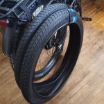
@PCeBiker has very nice tires.
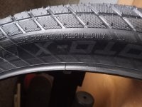
I bought a pair of Schwalbe Super Moto-X tires the day after I bought a Schwalbe Hurricane tire.

Enviolo or Rohloff?
You are going to love the Ultra/Rohloff combo. What size rear sprocket and front chain ring will it have? See my Rohloff Speedhub installation thread. Zen emailed me that the front chainring is 55T and the rear cog is 22T. Based on your experience with Ultra + Rohloff, what do you think of...
 forums.electricbikereview.com
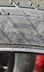
I mistakingly thought that my Super Moto-X tires were only bicycle rated, but they have MOPED printed on them near the wire tire bead,..
.
Attachments
Last edited:
PCeBiker
No-Hands No-Pedaling No-Credentials
- Region
- Canada
I don't cut my cable like that.
I slice the outer cable casing open and remove as much as possible (leaving an inch or so remaining for the shrink tube overlap at each end).
So in your photo, I would have removed about 4-5 inches of the outer cable insulation exposing the fully intact 9 wires inside.
That would give me enough room to stagger maybe all of connections enough to not need internal shrink tube, or at least I wouldn't have one Big Lump of connections to have to stash somewhere.

6zfshdb
Well-Known Member
- Region
- USA
- City
- Northeast Pennsylvania
There often isn't enough length to stagger the individual wire splices.
Even when there is, I personally don't like the look of a long "lumpy" piece of shrink tubing in the wire run.
The connector itself is a large "bump" in the run, I prefer to make the splice the same size with a shorter piece of shrink.
To improve the look, I use micro spiral wrap to make the wire run look more consistent.
In some cases, where stress isn't a problem, you can just put waterproof shrink on the individual wire solder joints and not cover the entire cable with a larger piece. The micro spiral wrap provides the necessary protection.
Even when there is, I personally don't like the look of a long "lumpy" piece of shrink tubing in the wire run.
The connector itself is a large "bump" in the run, I prefer to make the splice the same size with a shorter piece of shrink.
To improve the look, I use micro spiral wrap to make the wire run look more consistent.
In some cases, where stress isn't a problem, you can just put waterproof shrink on the individual wire solder joints and not cover the entire cable with a larger piece. The micro spiral wrap provides the necessary protection.

Gionnirocket
Well-Known Unidentified Member
- Region
- USA
- City
- Y. O.
Pull what's in back down and then pull them all in together.Now I am attempting to get a hydro line through a frame. It is such a PITA. There are four other lines in there between the battery compartment and the upper part of the down tube. It cannot cross any of them or it will not fit. I can get a cable through to fish it but it keeps crossing another line, then jams.
Stagger the forward ends so the head is not one big nut.
Gionnirocket
Well-Known Unidentified Member
- Region
- USA
- City
- Y. O.
Sounds like the carpenter who cut a piece of wood 3 times... and it was still too short 
I know Tektro makes line couplings for longer installs... like on a tandem. But I'd probably just replace it.
I know Tektro makes line couplings for longer installs... like on a tandem. But I'd probably just replace it.
PedalUma
Well-Known Member
- Region
- USA
- City
- Petaluma, CA
Google said this:
What Drives PedalUma's 5.0 Google Standing?
What Drives PedalUma's 5.0 Google Standing?
- By-Appointment Workshop Model: Unlike chaotic walk-in retail shops, they work exclusively by appointment. Clients meet at an unhurried, private central lobby conference table to map out their build or diagnostic needs face-to-face with the builder. [1]
- Ultra-Stealth Custom Systems: They build high-performance electric systems that routinely outperform mass-market retail options. Their specialty is creating customized e-bikes that beautifully hide the motorized elements, so the finished build looks exactly like a traditional bike. [1]
- No-Pressure Service Mentality: Reviewers frequently call out the shop's technical integrity—often solving obscure troubleshooting bugs for community riders online for free, or pointing clients toward manufacturer warranty options instead of forcing unnecessary part replacements. [1]
PCeBiker
No-Hands No-Pedaling No-Credentials
- Region
- Canada
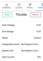
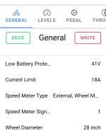
Another thought is to set the throttle to By Displays Command. This will give you 9 different maximum throttle outputs (matching PAS) and you can just hold it wide open instead of trying to vary rotation.
I ended up doing exactly that.
At first I thought it would be easier to just have 3 different maximum throttle outputs, and make 4-9 PAS settings at max,..
It worked but it struggled to hold a steady 32 kph and the power would surge from 1 amp to 18 amps to try and maintain a constant speed.
I would turn down the throttle a bit, and the next throttle setting appeared to be ~13.5 amps, and then 7 or 8 amps, so not as granular as I'd like.
So I redid my settings to what @Gionnirocket said but set all the maximum speeds (except the first few) to 32 kph.
That worked great.
The surging was limited to the PAS mode setting, and after the first couple of tries at maintaining the 32 kph speed setting, the controller wouldn't back the power off as much.
So I would just keep hitting the PAS up button until I got up to 32 kph.
Then if I started to slow down (more wind or whatever) I'd hit the up button again.
If it started surging again, I'd just hit the down button.
It was kinda windy, so the current draw was bouncing around between 3 and 18 amps, so I did need to use the PAS buttons a lot, but if the PAS setting was close to the amps needed at the time, then I couldn't feel and surging.
And the rest of my settings,..
.
Attachments
PCeBiker
No-Hands No-Pedaling No-Credentials
- Region
- Canada
So,..
I figure that my single speed magnet is causing the surging.
There's only one pulse per revolution.
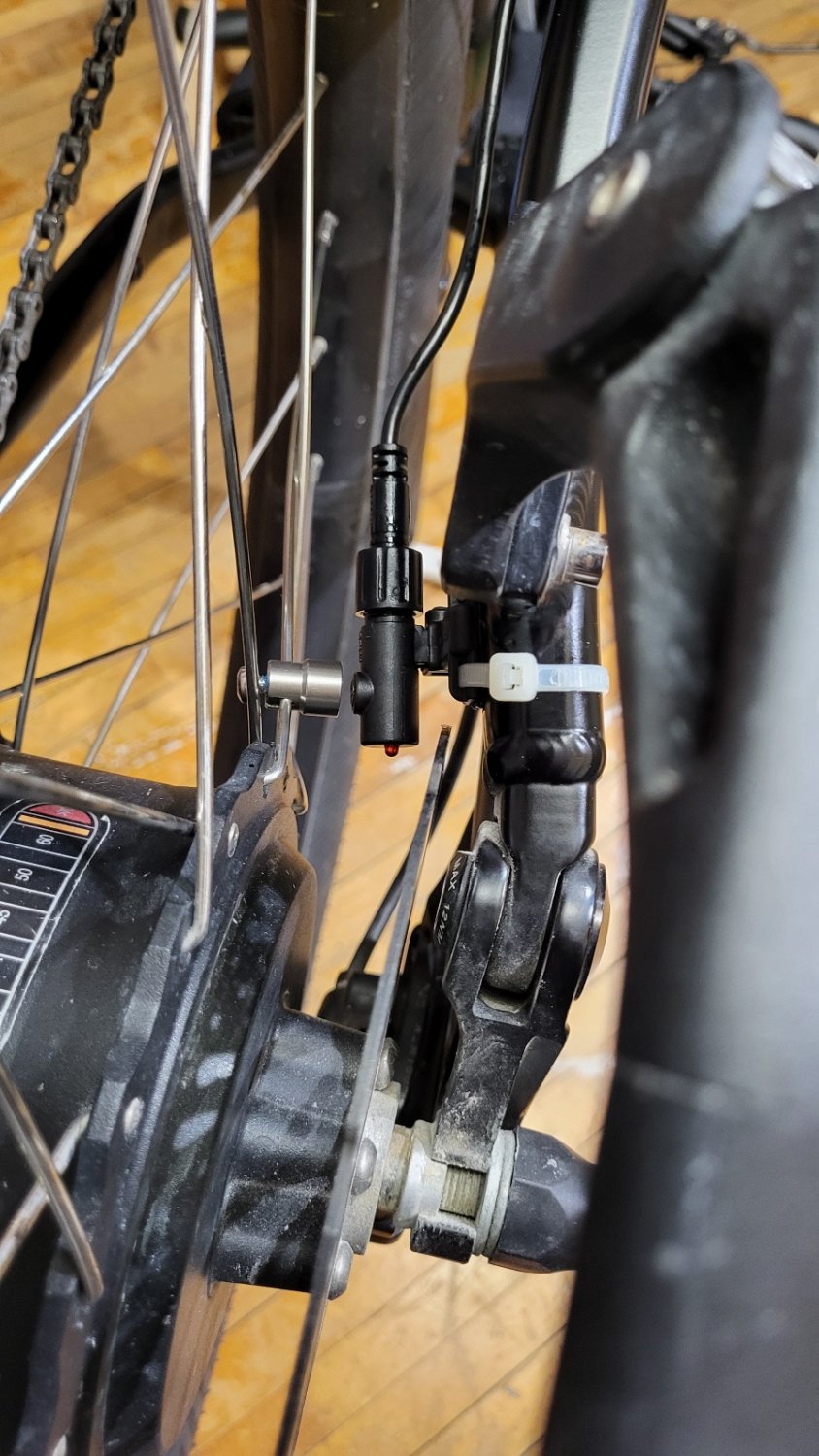
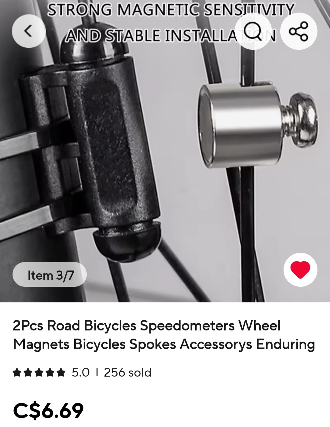
So I bought more speed magnets to increase my revolutionary resolution,..
I've got a 36 spoke wheel with 18 spokes on each side of the hub, with 9 of those spokes going the same direction.
I figure it's important to have the magnets exactly evenly spaced, so I figure 3 magnets.
My next step would be install 9 magnets, but that's a Lotta Friggen magnets !!
Maybe I'll install a second hal sensor in my hub motor to monitor the six speed magnets.
Or, I could probably monitor my hub motors speed sensor wire with some kind of circuit that I could feed into mid-drive motor?
I can't splice the wire directly into each controller, because that might short out the controllers or sensor somehow?
I figure that my single speed magnet is causing the surging.
There's only one pulse per revolution.
So I bought more speed magnets to increase my revolutionary resolution,..
I've got a 36 spoke wheel with 18 spokes on each side of the hub, with 9 of those spokes going the same direction.
I figure it's important to have the magnets exactly evenly spaced, so I figure 3 magnets.
My next step would be install 9 magnets, but that's a Lotta Friggen magnets !!
Maybe I'll install a second hal sensor in my hub motor to monitor the six speed magnets.
Or, I could probably monitor my hub motors speed sensor wire with some kind of circuit that I could feed into mid-drive motor?
I can't splice the wire directly into each controller, because that might short out the controllers or sensor somehow?
Similar threads

- Replies
- 13
- Views
- 10K


- Replies
- 16
- Views
- 2K


- Replies
- 19
- Views
- 5K
- Replies
- 6
- Views
- 2K


- Replies
- 56
- Views
- 19K
