You are using an out of date browser. It may not display this or other websites correctly.
You should upgrade or use an alternative browser.
You should upgrade or use an alternative browser.
I finally took my ebike for a test ride.
- Thread starter PCeBiker
- Start date




Gionnirocket
Well-Known Unidentified Member
- Region
- USA
- City
- Y. O.
Yes I put shrink wrap on tucked away connectors.
And when necessary, just a drop of silicone grease. Less is MORE!!
If you would have pinned it out when it happened (as suggested) you would have found the issue then.

¡I'M BATMAN!
And when necessary, just a drop of silicone grease. Less is MORE!!
If you would have pinned it out when it happened (as suggested) you would have found the issue then.
¡I'M BATMAN!

PCeBiker
No-Hands No-Pedaling No-Credentials
- Region
- Canada
Yes I put shrink wrap on tucked away connectors.
I did consider it at first, but I didn't want to make the connection any Fatter.
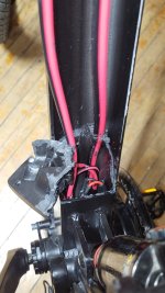
The downtube is crammed full of wires.

And when necessary, just a drop of silicone grease. Less is MORE!!
I figured none is best.
Everything was covered in dust. I didn't want it to stick.
If you would have pinned it out when it happened (as suggested) you would have found the issue then. View attachment 212412
¡I'M BATMAN!
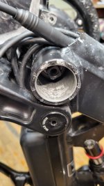
I had to remove the motor to get to the connector, so I was procrastinating.
I just used my hub drive and ignored the issue

So,..
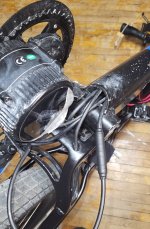
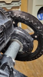
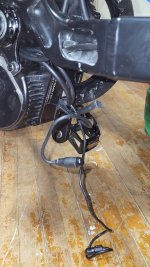
I managed to get my motor removed, and reinstalled then noticed my speed sensor wire had fallen between the chain wheel and motor housing and was trapped.
Not enough room to pull the connector through.
So the whole motor had to be loosened off again.
Just a few mm this time.
Fortunately, I got it all up and running, and decided to plug in my programming cable to check my settings,..
WTF??!!
I kept trying, but it wouldn't connect !!
And why is it plugged into my display? Shouldn't it be plugged into the controller??
My hub drive has the identical display, but the plugs are all reversed to keep people from doing stupid things.
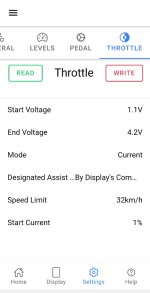
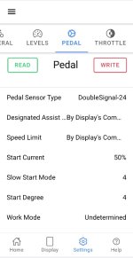
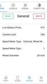
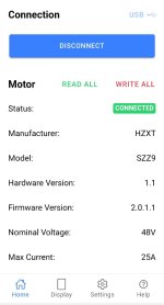
So,.. after connecting my programming cable to my Mid-drive motor, I got a look at my settings,..
Attachments
-
 Screenshot_20260709_174112_Speeed.jpg55.1 KB · Views: 66
 -
 Screenshot_20260709_174136_Speeed.jpg64.5 KB · Views: 67
 -
 Screenshot_20260709_174155_Speeed.jpg53 KB · Views: 70
 -
 Screenshot_20260709_174226_Speeed.jpg52.6 KB · Views: 75
 -
 20260709_160228.jpg226.7 KB · Views: 63
 -
 20260709_160233.jpg194.1 KB · Views: 62
 -
 20260709_182051.jpg191.6 KB · Views: 64
 -
 20260709_182110.jpg392.1 KB · Views: 65
Last edited:
Gionnirocket
Well-Known Unidentified Member
- Region
- USA
- City
- Y. O.
Silicone grease is not necessary for a concealed connector... but if only to aid with disassembly in the future. Dust wouldn't be a problem as I would only apply it to the plastic on the julet and it'll be under the shrink wrap.
You connect to the display as that cable has communication with the controller (Tx/Rx wires)
As for your LEVELS settings.... You're going to have to play with them and find what works. Mine was set up for pedaling and to eliminate ghost pedaling so a much different approach. Throttle was used minimally.
Additionally I used the % toggle as that's how the PC interface works and by the time the SPEEED APP came around I was used to working around those numbers.
If you have any questions or something isn't doing what you want... Post it and we'll figure it out
You connect to the display as that cable has communication with the controller (Tx/Rx wires)
As for your LEVELS settings.... You're going to have to play with them and find what works. Mine was set up for pedaling and to eliminate ghost pedaling so a much different approach. Throttle was used minimally.
Additionally I used the % toggle as that's how the PC interface works and by the time the SPEEED APP came around I was used to working around those numbers.
If you have any questions or something isn't doing what you want... Post it and we'll figure it out


PCeBiker
No-Hands No-Pedaling No-Credentials
- Region
- Canada
With no speed sensor I'm surprised it didn't throw an error 21... typically shutting off assistance.
Not sure what's going... post your settings
I just noticed today that I am getting error code 21, but my motor keeps going using the throttle. I dunno

I guess I'll install the speed magnet but I'm in no rush.
(That's bugging me too, cuz I don't wanna unbalance my wheel. Maybe I'll install two to balance it out.
)Right now, I'm overthinking the brake switch installation.
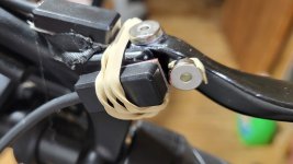
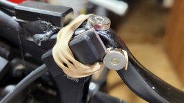
It looks like I only get one shot at installing them, and they aren't sitting flush on the brake lever, so I'm thinking of building up a level surface with hot glue?
I found a video, but it won't work with my brake levers.
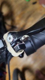
I managed to get a brake sensor installed.
And the display,..
The lever position when the brake light comes on,..
And when the rear brake starts to grab,..
(I swapped my brake lines.)
Now I can use the left brake lever like a clutch to stop power to the motor when I shift gears, without the brake grabbing.
There's still plenty of lever movement to lock up my rear wheel.
I couldn't install them on the bottom like in the video
PCeBiker
No-Hands No-Pedaling No-Credentials
- Region
- Canada
I couldn't install them on the bottom like in the video
The magnet just rolled around in front of the sensor.
It didn't move away from it,.
They said in the video it's best to crazy glue the magnets in place, so I got all carried away and sanded the lever under the magnet to bare metal and roughed it up with 120 grit sand paper, then cleaned it with acetone.
I wiped the other part of the lever with acetone then built it up with black hot glue.
Attachments
Last edited:
Gionnirocket
Well-Known Unidentified Member
- Region
- USA
- City
- Y. O.
Yeah that's how I have mine adjusted...
The cut out works just before the pads engage. I use it sometimes squeezing through the path narrow openings so I can pedal with no need to change PAS down and then on the other side I'm already in the PAS desired... and ready to launch quickly.

Tektro has hydro handles with cutouts if the current setup ends up being a pain in the ass.
I never tried the throttle without the speed sensor working??
I wouldn't worry about wheel balance... but if it bugs you, just mount it as close to wheel center as possible. There is the option in the programming to use 2 magnets but many have posted that it's no better than one.
The cut out works just before the pads engage. I use it sometimes squeezing through the path narrow openings so I can pedal with no need to change PAS down and then on the other side I'm already in the PAS desired... and ready to launch quickly.
Tektro has hydro handles with cutouts if the current setup ends up being a pain in the ass.
I never tried the throttle without the speed sensor working??
I wouldn't worry about wheel balance... but if it bugs you, just mount it as close to wheel center as possible. There is the option in the programming to use 2 magnets but many have posted that it's no better than one.
PCeBiker
No-Hands No-Pedaling No-Credentials
- Region
- Canada
You connect to the display as that cable has communication with the controller (Tx/Rx wires)
It doesn't actually.
The display connector comes apart, and you plug the programming cable into the end of the connector that it will plug into.
It only connects to the display when you plug it into the wrong display.
My hub motor has an identical display and connector, but the male/female ends on the connector are reversed.
The programming cable only "connected" when I plugged it into the Mid-drive connector, and that cable end was going to the controller, while the display remained disconnected.
Perhaps using the Y-connector you posted allows the programming cable to be installed "in-line" between the display and controller, so everything is connected, and working, and programmable at the same time?
As for your LEVELS settings.... You're going to have to play with them and find what works. Mine was set up for pedaling and to eliminate ghost pedaling so a much different approach. Throttle was used minimally.
The fact that I don't pedal makes everything WAY Easier to setup and program.
Additionally I used the % toggle as that's how the PC interface works and by the time the SPEEED APP came around I was used to working around those numbers.
I got used to showing power in "watts" for both my ebikes, then decided to switch to "amps" for my Voltbike, and got used to that.
I want to allow my ebike to go 32 kph with Any amount of power applied to the motor.
If it can go 32 kph using 1 amp, and 50 watts, then let it go 32,..
If you have any questions or something isn't doing what you want... Post it and we'll figure it out
I remember @AHicks helping me with getting my KT controller and display set up and running.
One thing that I wanted to do was give my motor a Constant power of say,.. 100 watts continuous with no speed limit, but it wasn't possible with the KT controller.
If I set up "Throttle Gear #1" to have 100 watts, it also limited the speed in that throttle gear.
I remember @6zfshdb posting about the waste involved with PAS modes trying to maintain a constant speed, and the power is always pulsing up and down all the time being wasteful.
I had Huge Range Anxiety when I got my first ebike and wanted to go as far as possible on a charge. (without pedaling, of course)
When I got my 25ah battery, I managed to go 85 km from fully charged to the battery shutting down, but it took me 5½ hours.
I had a very soar ass.
Gionnirocket
Well-Known Unidentified Member
- Region
- USA
- City
- Y. O.
You misunderstood.... You originally asked why you were plugging in to the display cable and not the controller directly. But the display cable is directly connected to the controller and has the Tx/Rx wires as the display needs to communicate with the controller as well.It doesn't actually.
The display connector comes apart, and you plug the programming cable into the end of the connector that it will plug into.
It only connects to the display when you plug it into the wrong display.
My hub motor has an identical display and connector, but the male/female ends on the connector are reversed.
The programming cable only "connected" when I plugged it into the Mid-drive connector, and that cable end was going to the controller, while the display remained disconnected.
Perhaps using the Y-connector you posted allows the programming cable to be installed "in-line" between the display and controller, so everything is connected, and working, and programmable at the same time?
The fact that I don't pedal makes everything WAY Easier to setup and program.
I got used to showing power in "watts" for both my ebikes, then decided to switch to "amps" for my Voltbike, and got used to that.
I want to allow my ebike to go 32 kph with Any amount of power applied to the motor.
If it can go 32 kph using 1 amp, and 50 watts, then let it go 32,..
I remember @AHicks helping me with getting my KT controller and display set up and running.
One thing that I wanted to do was give my motor a Constant power of say,.. 100 watts continuous with no speed limit, but it wasn't possible with the KT controller.
If I set up "Throttle Gear #1" to have 100 watts, it also limited the speed in that throttle gear.
I remember @6zfshdb posting about the waste involved with PAS modes trying to maintain a constant speed, and the power is always pulsing up and down all the time being wasteful.
I had Huge Range Anxiety when I got my first ebike and wanted to go as far as possible on a charge. (without pedaling, of course)
When I got my 25ah battery, I managed to go 85 km from fully charged to the battery shutting down, but it took me 5½ hours.
I had a very soar ass.
The Y cable only facilitates not having to unplug the display to connect for programming. I was trying a lot of different things when I first got it so it made things easier and there is no wear or possible pin damage because I wasn't repeatedly unplugging the display.
PCeBiker
No-Hands No-Pedaling No-Credentials
- Region
- Canada
Yeah that's how I have mine adjusted...
The cut out works just before the pads engage.
My cut out switch activates Well before the pads engage, so I don't have to worry about dragging the brake, or having the motor kick back on because I didn't pull the lever far enough.
I use it sometimes squeezing through the path narrow openings so I can pedal with no need to change PAS down and then on the other side I'm already in the PAS desired... and ready to launch quickly.
I'm sure that I'll be able to use it that way, but I'm mostly wanting to use it as a "clutch" or "shift sensor" without installing a shift sensor.
Tektro has hydro handles with cutouts if the current setup ends up being a pain in the ass.
Yeah, that's what I've got, but I'm using those switches for my hub motor.
The hub motor supplies the +5V to brake switches, and I don't want to feed that +5V into both motors.
That's not a good idea.
I remember you and @6zfshdb discussing an isolation circuit with relays to isolate the brake switch outputs, but that setup sounds like more of a pain in the ass than gluing magnets to my levers.
I should be fine, unless my magnets or switches fall off?
I wouldn't worry about wheel balance... but if it bugs you, just mount it as close to wheel center as possible.
Thanks.
I didn't think of that.
A magnet mounted right beside a 15 pound hub motor (or whatever it weighs?) isn't gunna throw my wheel outta balance.
I know that if I install it I can at least limit my speed to 32 kph.
I'm pretty sure that I was going faster than 32 kph without any speed data?
There is the option in the programming to use 2 magnets but many have posted that it's no better than one.
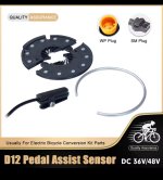
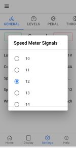
Maybe I can install one of these around my rear axle and set my program up for 12 ??
Attachments
Gionnirocket
Well-Known Unidentified Member
- Region
- USA
- City
- Y. O.
I didn't want that much play in the brake levers cut out point. I rest my fingers on the levers often (carpal tunnel) and a slight bump could activate cut out.
PCeBiker
No-Hands No-Pedaling No-Credentials
- Region
- Canada
You misunderstood.... You originally asked why you were plugging in to the display cable and not the controller directly.
It all started with me smoking too much Vado (which the polish guy has now effectively banned from this forum) and plugging my programming cable into my hub motor instead of the mid-drive motor.
I disconnected the display connector, and simply plugged in the programming cable into the connector that it would plug in to.
I knew that normally the controller powers the display, but the programming cable plugged into the display end of the connector, so is my Smartphone supposed to power the display now through the programming cable??
That doesn't seem right at all??
I had programed it months earlier. Why doesn't it work now??
I was plugged into the wrong display upside-down and backwards.
I coulda blowed s*it up if I managed to plug it into my hub drive controller?
I mighta blowed up my phone?
The Y cable only facilitates not having to unplug the display to connect for programming. I was trying a lot of different things when I first got it so it made things easier and there is no wear or possible pin damage because I wasn't repeatedly unplugging the display.
I did trim away the rubber around the programming cable connector like you showed, and I lubed my connectors with electronics safe synthetic oil instead of the grease.
Works way better.
I don't think that I need to get too carried away with programming except for guesstimating the power delivery curve for my 9 "Throttle Gears" (PAS modes)
Power delivery has an inversed relationship with wind speed like that stupid 000 gauge wire.
It's based on the circular mil area (thickness) of the wire.
I'm pretty sure power is inversely related to the cube, or even quadruple of wind speed?
I'm gunna smoke a Vado and think about it.
1÷ 2³ or
1÷2⁴ ??
Wire gauge (IIRC) would be
1÷2² (with a piece of
 in there to round things out.)
Maybe @kevinmccune can help me out with an inverse quadratic equation for my throttle gears?
I used to this stuff in 1982.
I don't member nuthin now.
Last edited:
PCeBiker
No-Hands No-Pedaling No-Credentials
- Region
- Canada
I didn't want that much play in the brake levers cut out point. I rest my fingers on the levers often (carpal tunnel) and a slight bump could activate cut out.
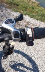
I ended up loosening up my rear brake pads a bit to give me more lever movement.
The brake pads were grabbing just after the brake switch, and I kept either dragging the brake or having the motor kick back on.
Now I never kill the motor by accident, or drag my rear brake, and I can still lock up the wheel.
I use it to kill the motor and coast to a stop All the time.
I just leave my throttle locked. (at whatever speed it's set at)
Then I release the brakes when I'm ready to go, and the ebike returns to set speed,..
My front brake (on the right side now) activates the pads with far less lever movement.
(I don't use that lever like a clutch or shift sensor.)
Attachments
PCeBiker
No-Hands No-Pedaling No-Credentials
- Region
- Canada
,.. It has an American bottom bracket and a one piece cast iron crank.
I remember those.
You had to weave the whole thing into the BB after removing everything from the crank.
I think that both bearing cups needed to be pressed out, and you couldn't get in there to get at the chain wheel side?
I think we reached in with a flat head screwdriver and pounded it out??
The bearing cups didn't thread into the BB of the frame.
PCeBiker
No-Hands No-Pedaling No-Credentials
- Region
- Canada
I was about 12 yrs old when my freind and I dealt with that.
I still remember??
We didn't have no fancy tools.
We just used big flat head screwdrivers, hammers, and the ViseGrip pliers that I still have.
There's bearing races machined into the crank, and they don't fit through the bearing cups, so both cups need to be removed.
I still remember??
We didn't have no fancy tools.
We just used big flat head screwdrivers, hammers, and the ViseGrip pliers that I still have.
There's bearing races machined into the crank, and they don't fit through the bearing cups, so both cups need to be removed.
PCeBiker
No-Hands No-Pedaling No-Credentials
- Region
- Canada
,.. It will save almost ten pounds
So how much does it weigh if it's ten pounds heavier than the replacement?
I thought my 15 pound battery was bad, but it's well worth it to me.
I didn't even need my BB crank until I added the mid-drive motor.
PCeBiker
No-Hands No-Pedaling No-Credentials
- Region
- Canada
I thought I'd post my throttle results here so that hopefully I can find them when I forget it all.
So,.. power on, no throttle,..
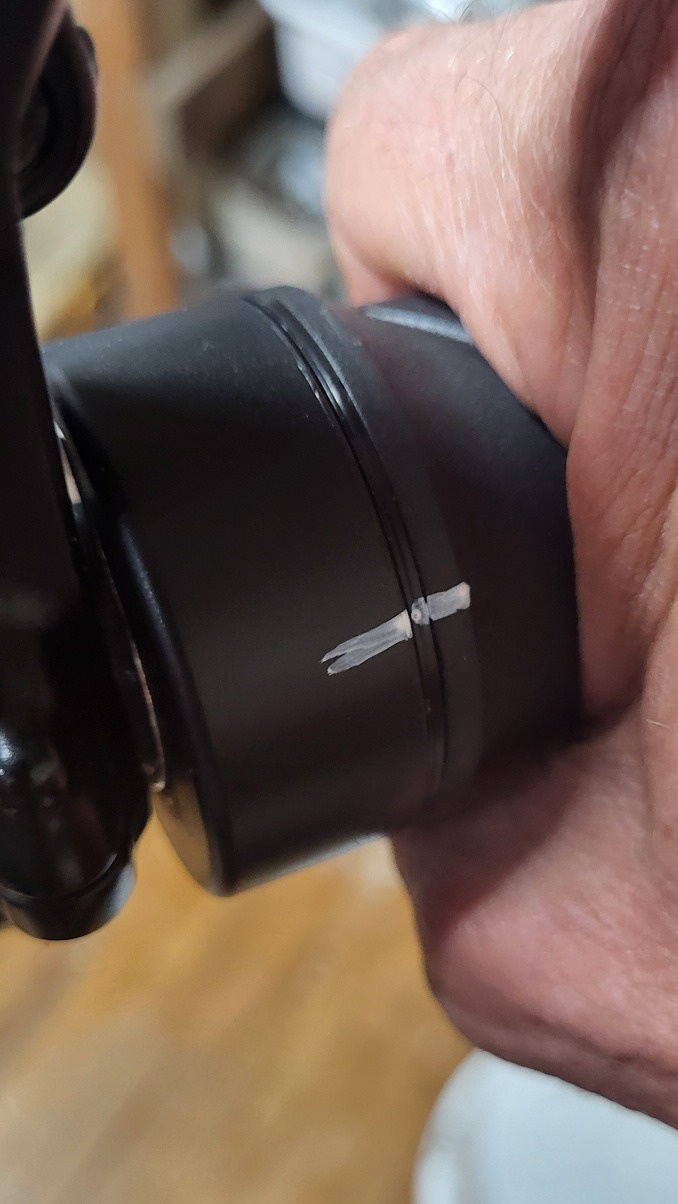
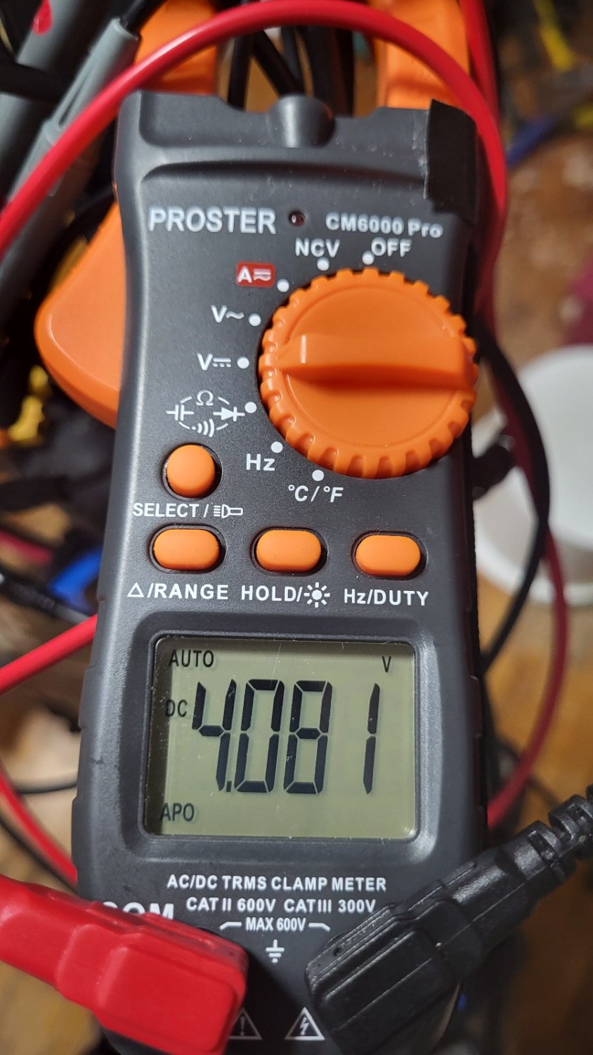
Motor turns on,..
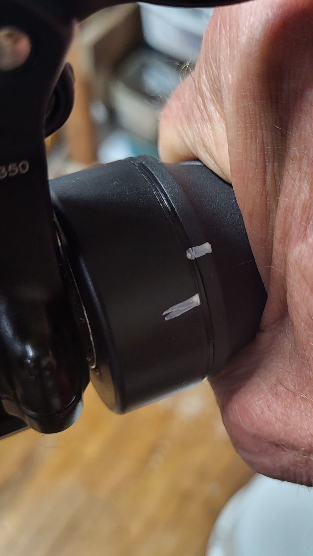
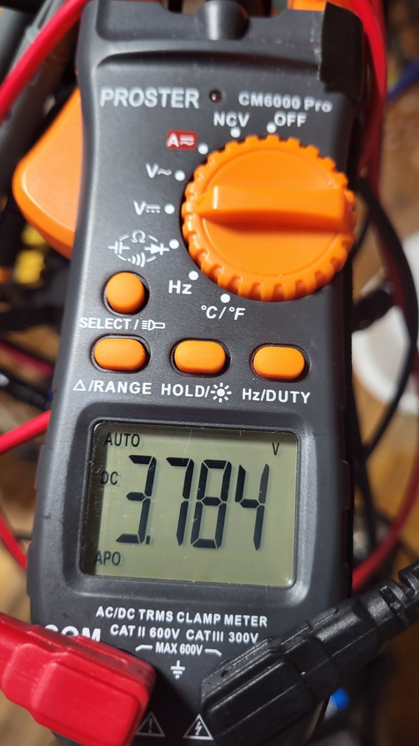
Then the throttle voltage dropped gradually and evenly to,..
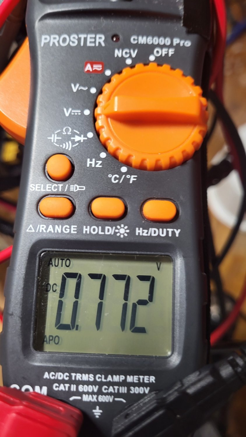
So,..
It does look like I can adjust my throttle input voltage down to 0.772 V and get a Really Big Sweep Angle ??!!@
I didn't have any load on the motor though, and it sounded the same from the start of throttle operation to the end of rotation, so I don't know how it will behave under load on the road ??
So,.. power on, no throttle,..
Motor turns on,..
Then the throttle voltage dropped gradually and evenly to,..
So,..
It does look like I can adjust my throttle input voltage down to 0.772 V and get a Really Big Sweep Angle ??!!@
I didn't have any load on the motor though, and it sounded the same from the start of throttle operation to the end of rotation, so I don't know how it will behave under load on the road ??
PCeBiker
No-Hands No-Pedaling No-Credentials
- Region
- Canada
It does look like I can adjust my throttle input voltage down to 0.772 V and get a Really Big Sweep Angle ??!!@
My current settings that I'm gunna change,..
Interestingly, the "start" voltage is set to 4.2 volts, but when the motor first starts, it reads 3.78 V.
And the "end" voltage (maximum throttle) is 0.77 V but it's set to 1.1 V
(That whole reverse voltage thing for a mid-drive throttle)
I need to do a load test to see if I can make sense of the numbers.
The motor just spins right up to speed with only a 1 or 2 amp draw. Changing "throttle gears" had no effect on the motor.
So I guess the motor is going 32 kph with only ~50 watts ??
Last edited:
Gionnirocket
Well-Known Unidentified Member
- Region
- USA
- City
- Y. O.
To me it appears as everything is backwards... Even the throttle rotation.
It should be the lower V at start (at rest) ... Somewhere around 1.0v (you can see that in the controller default settings)
Are you sure you have Bafang BBS* compatible hardware?
Where do you have the test leads connected to?
You should be on pins 7 and 8.
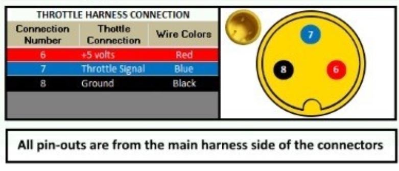
And yeah... With no load it pretty much appears to act like on/off
Under load you will see/feel the current vary.
It should be the lower V at start (at rest) ... Somewhere around 1.0v (you can see that in the controller default settings)
Are you sure you have Bafang BBS* compatible hardware?
Where do you have the test leads connected to?
You should be on pins 7 and 8.
And yeah... With no load it pretty much appears to act like on/off
Under load you will see/feel the current vary.
Last edited:
PCeBiker
No-Hands No-Pedaling No-Credentials
- Region
- Canada
To me it appears as everything is backwards... Even the throttle rotation.
The throttle for the mid-drive is on the left and twists in the normal direction.
I was standing in front of my ebike looking at my voltmeter, twisting the throttle with my right hand.
To me it appears as everything is backwards...
Yeah, I was probing the wrong wires,..
So,.. Here's the redo.
Power on, no throttle,..
Motor turns on,..
Then the throttle voltage gradually increased to this, using Way more throttle rotation than my hub-drive throttles.
That 0.820 V throttle output at startup would throw a code, and shutdown the throttle with my KT controller (and I think all hub motors and throttles?).
The voltage needs to be above ~1.1 V
Similar threads

- Replies
- 13
- Views
- 9K


- Replies
- 16
- Views
- 2K


- Replies
- 19
- Views
- 3K
- Replies
- 6
- Views
- 2K


- Replies
- 56
- Views
- 11K
