Bafang 750 Watt, Integrated Wheel, Rear Hub Fat Bike Motor

I don't have anything but the blurry pictures you've posted to go on, but it looks like there are 6 notches arranged around the outside of the main 3 wires on the one side. All but impossible to tell, is if those "notches" line up with the small pins on the other side?

Regarding matching the new vs. old wires, are you considering wire splices, or soldering a new pigtail on to your controller board? If planning a board level mod, I would highly discourage that.
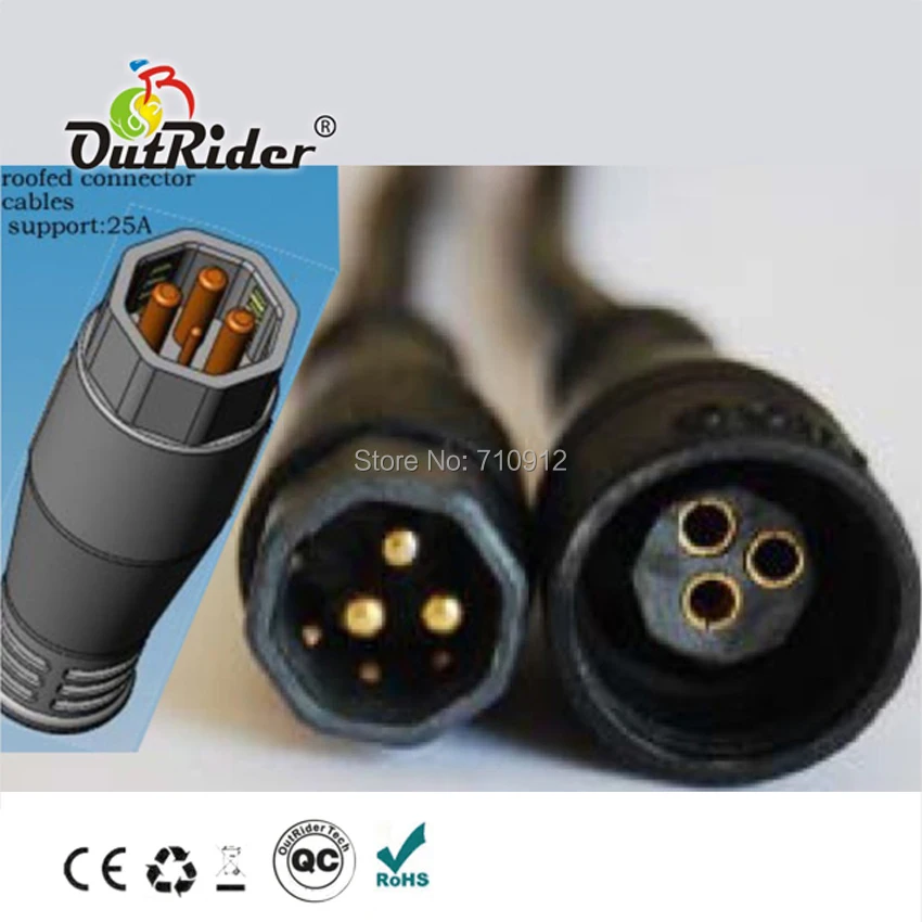
 
I was going to follow @harryS recommendation to splice in the box, not on the board. I have to believe the notches do not line up, as I cannot get to 2 motor connectors to *plug in*.

I cleared it up as best I could...
20200704_085926.jpg
 
Last edited:
Well, if nothing else, it sure looks like a match from where I'm sitting.
 
Arrows on a connector s don't line up when it appears pins do. I was at this for a while I wonder if the 25 amp controller, which mentioned 750 watt fat bike, is slightly different, and would work.
 
I don't have anything but the blurry pictures you've posted to go on, but it looks like there are 6 notches arranged around the outside of the main 3 wires on the one side. All but impossible to tell, is if those "notches" line up with the small pins on the other side?

Regarding matching the new vs. old wires, are you considering wire splices, or soldering a new pigtail on to your controller board? If planning a board level mod, I would highly discourage that.

I also have no idea on the connectors.. From his original description, I said the new controller and old motor connectors wouldn't match. Then he said they worked fine, so I figured I was wrong and dropped out of the discussion.

I will stand by my earlier advice. If you have to splice a 9 pin cable, do it inside the controller box. It's far easier and makes for a more reliable splice. No need to connect to the circuit board pads. Just connect to the wires.
 
If I had the right connector, I'd attempt this ASAP. I have one on the way - potentially (but could be the same thing). The only sticking point is having to disable the OLD controller to salvage the connector. I'd like to do a dry run without disabling anything.

I'm still unsure about the speed sensor, and what predicates having to use an *external* sensor. There is no external sensor now (no magnet sensor mounted on the spokes), and I'm assuming that it is built into the controller, measuring MPH whether coasting, pedaling, or throttling. Will the new controller measure MPH with the new display?
 
Is the connector coming out of the motor a 9 pin male connector or a 9 pin female? Picture of it, and only it?

DOn't worry about the speed sensor. Your answers say you have one in the motor, and when you connect the motor to the new controller (and enable the speed sensor in the LCD settings), it will work.
 
Here's another shot of the 9 pin connector coming FROM the motor, obviously male. Good news on speed sensor.

20200616_085020.jpg
 
With a little enhancement. Isn't that like your original RAD connectors, Ahicks?
IMG_0294.JPG


There aren't that many styles. I think the above was for bigger 750+W motors, as the other 9 pin connector isn't intended for high current. So I would expect the original KT that the OP has would work.

Have you connected it, added a battery and tried to see if the throttle works? If the motor cable is wrong you will get an Error 03, Hall Sensor.

If it doesn't fit, maybe this is the extension for 24 bucks.

This is probably an extension.
 
@harryS

That connector IS an extension, yes.

BIG NEWS
Okay, connected!!! - with arrows at about 30 degrees off, added battery, and the throttle works! Seems like RPM is higher (judging by sound)
No error message, but also no MPH or PAS (currently hooked up to old PAS, haven't installed new one).

UPDATE
Just gave it a try with the old display, and got the error message 30 Maintenance vs 03. Also no MPH or PAS with old display.

UPDATE 2
I found a video on the KT display. Breaks it down really nicely, and much easier to work with the 8H grid screen.

After going through all the suggested settings for the Bafang 750 watt hub motor, I'm still no closer to MPH, PA, or even the light working. The only thing I'm using on the current set up is the motor and PA sensor, all else is the PSW kit parts, controller, harness. Only thing that does work is the throttle.
 
Last edited:
Your old LCD is not compatible with a KT controller. It may light up and fool you that it's working, but it cannot communicate (wrong protocol). You can look up error 30 for your old display.

The same thing could happen with the LCD8H with a wiring fault. It will power on and you can change P and C settings, but not work. However, it would throw an error if it couldn't read the controller. Not showing a speedometer number is not not something I've ever noted. My LCD3 always had the speed when the motor was running (not coasting), even if I didn't have a speed sensor. However, maybe you need to look at your P2 number. If set to 0, maybe the LCD8H shows nothing.

You can also hold the down button and that should initiate a 6km/hr walking speed out of the motor, another test to show the display is hooked up and working.
 
I figured the old display wasn't compatible with the KT (error 30 said *maintenance*).

I have changed P2 settings from 0 to 6, and in everything between. So it's not the P2 # exclusively. The LCD3 you have is the exact same thing as the LCD8H, except a better interface (according to video). I've looked at all the P and C settings, and they all seem correct.

The new display also doesn't display watts being used as I crank the throttle. It does show battery volts (at about 58 with 52 volt battery), but the battery icon shows empty.

Like I said, it does throttle with what seems like full power. I'll try the walk test (hold down button).


Some Thoughts
Been trying to find an answer to this, really makes no sense at this point. I'm using all KT parts - controller, harness, throttle, light (brakes not hooked up yet) with current motor and PA. The display reads out nothing but ambient temp and volts. The light also doesn't work when turned on on display.

This should work independently of my bike, kind of just borrowing my bike's motor and PA to test this new controller / display / throttle.

Been reading about the Higo connector and pins - 3 pins plus 6 hall sensors. Could one of the sensors be off because the arrows don't line up on the Higo connectors? Wouldn't I get an error code?

I wonder if the 22 amp controller from PSW would have the same issues, or been powerful enough (currently it's a 25 amp controller, but looks absolutely identical to the 22 amp from PSW).

36V/48V 750W 22A 9Mosfet Waterproof Sinewave ebike Electric bicycle Brushless Controller fit bafang MXUS 750W fat motor

VS

36V/48V 1000W 35A 12Mosfet XT60 Waterproof Sinewave ebike Electric bicycle Brushless Controller fit bafang MXUS motor
 
Last edited:
9 Pin motor cable arrived from ebike world. It fits the motor perfectly, and the new controller just like the original (arrows at about 30 degrees off). Throttle works. I can use this cable inside my new controller.

Before I attempt this splice job, any tips...
 
That is strange isn't it. Yet the motor works, and those pins have to be in the right spot for that to happen. Pull the motor cable. Turn the throttle. You should get a error indicating the motor connections are bad.
 
Very strange and a bit discouraging. I pulled motor plug, turned throttle, no error. Using a multimeter, I determined that this is the current way the plugs are wired on extension cable (see pic). Perfect mirror image. Not sure how to do this for the motor plug, or current controller plug. I can touch the multimeter to the controller pins, and circuit board and get resistance readings, not always zero. If I could identify which wire goes to which pin on the current controller cable, does that guarantee it will follow the same pattern?

20200706_152300.jpg
 
Last edited:
Nope. It's about firing order. The order in which the controller powers the 3 phase wires (123,123,123 for every revolution) must match the motor's phase wires. Kinda like wires muct be inserted into a distributer on a car motor. To get it to run smoothly, they MUST be in the correct order.

As there is 3 wires on each side, there's 9 possible combinations. With your stuff, any luck at all would have the colors matching on both sides of the plug. That's where I would start. Yellow to yellow, green to green and blue to blue. Then test with just the lightest amount of throttle to see what happens. If it works correctly, go ahead and wire everything permanently.

The sensor wires, also yellow green and blue, will follow the phase wires. After that, when you are running potential combinations down one at a time, if you have the yellow phase wire on one side hooked to the blue phase wire on the other, the sensor wires will follow suit (yellow to blue, etc).
 
What would explain the throttle working, but pretty much nothing else, in the current test phase (arrows off)? Are the phase wires correct, while sensor wires are not lined up in the connector with the arrows eschew?

You mentioned something about alligator clips to test this, do you recommend me using clips to create a temporary connection for testing, or is there a simple way to do this quickly?
 
Last edited:
Which controller is in play? Which throttle are we talking about, new or original? What exactly is "working"?

Unless you are talking about only the new components here, why would what "works" make any difference? Your final configuration will be different.

Simple is a relative term? I have a set of 12 16 ga wires that are about a foot long with an alligator clip on each end. That makes a job like this one pretty easy. If I did not have those, I would probably use wire nuts as a temporary connection. Once you have it running correctly, take it apart, one wire nut at a time, and make your final connection (w/solder/shrink wrap). -Al
 
Back