You are using an out of date browser. It may not display this or other websites correctly.
You should upgrade or use an alternative browser.
You should upgrade or use an alternative browser.
Bafang 750 Watt, Integrated Wheel, Rear Hub Fat Bike Motor


Bravesst
Active Member
That is the cable that is snaked through the frame from the display (lots of other stuff as well). These plugs do not pair. One says Julet, one says Lermew. Should I swap out this entire cable - seems to be a big job? Or just change a connector - if that is even possible?
BTW - @Timpo the 52v battery makes a bigger difference than I thought, but only when it's charged above 50%. I got 25mph down hill. And it seems to hold up longer - with lots of throttle I got about 20 miles with staying above 50% or so.
BTW - @Timpo the 52v battery makes a bigger difference than I thought, but only when it's charged above 50%. I got 25mph down hill. And it seems to hold up longer - with lots of throttle I got about 20 miles with staying above 50% or so.
AHicks
Well-Known Member
- Region
- USA
- City
- Snow Bird - Summer S.E. Michigan, Winter Gulf Coast North Central Fl.
How are you planning on using the NEW display, with the NEW controller? Don't those 2 plugs match?
My bet is, that your brakes and throttle will also need to plug into the NEW harness.
If you have to string the new display harness along or inside the frame, so be it! Shouldn't be that big a deal.
My bet is, that your brakes and throttle will also need to plug into the NEW harness.
If you have to string the new display harness along or inside the frame, so be it! Shouldn't be that big a deal.
Bravesst
Active Member
I agree, probably not a that big a deal to snake the cable, but it would also involve swapping out brake handles (different sensor and seem much cheaper made), throttle (even though old throttle works with new harness). I've never done any of this before, and not having to rebuild the brake system would be sweet.
It seems to me, it's all about the one harness cable from old harness to new controller, everything else will plug in (except battery, which I can easily change connectors).
As a side note, I have another bike on the way in July, and may wait to do these upgrades until I have my ride guaranteed.
It seems to me, it's all about the one harness cable from old harness to new controller, everything else will plug in (except battery, which I can easily change connectors).
As a side note, I have another bike on the way in July, and may wait to do these upgrades until I have my ride guaranteed.


AHicks
Well-Known Member
- Region
- USA
- City
- Snow Bird - Summer S.E. Michigan, Winter Gulf Coast North Central Fl.
Re: brake handles. This is your call. These are simple on-off switches. That's it! You can use your existing switches by installing the correct connector, or you can replace the handles and use the new ones with matching connectors. Those are your only options, switch the ends, or switch the handles.
SAME story with the throttle. Switch the end, or switch the throttle. To switch the end, you'll need to identify the 3 wires. One will be 5v+, one will be 5v-, and the remaining is the sensor wire.
If you want to use the old harness (which I think is a bad plan), you're going to need to confirm the function of every wire in it to allow you to change the plug. It's that simple (or not, depending on how you are looking at it).
Bravesst
Active Member
My experience with electronics is building a small appliance that is pretty standardized and self designed, hand made mostly of wood, with a single 18650 battery. If I ever have to join wires together, I use butt connectors. I tin everything, heavily, before soldering, even with connectors, but never just join wire to wire, solder, heat shrink. I need to adjust my mindset to a different approach.
I see now where the main thing I need to do is ID each wire. The actual connection is basic stuff. Big question, what is the best way to ID the wires?
It would be nice to have lots of extra connectors on hand.
 www.ebikeschool.com
I see now where the main thing I need to do is ID each wire. The actual connection is basic stuff. Big question, what is the best way to ID the wires?
It would be nice to have lots of extra connectors on hand.
How To Swap An Ebike Connector
www.ebikeschool.com
AHicks
Well-Known Member
- Region
- USA
- City
- Snow Bird - Summer S.E. Michigan, Winter Gulf Coast North Central Fl.
"Best" way differs depending on which one(s) we're talking about. I'll try to help, but you have to tell me if we're talking brake handle, PAS sensor, or throttle (very similar to the PAS sensor).
I'm afraid the main harness connector is beyond my patience level.
I will say that the light gauge of most wires you're working with require pretty light tinning. Nothing heavy required.
I'm afraid the main harness connector is beyond my patience level.
I will say that the light gauge of most wires you're working with require pretty light tinning. Nothing heavy required.
Bravesst
Active Member
I apologize for the confusion. I'm doing the best I can with everything new. And I really appreciate the time and effort.
The throttle connectors are the same, which means I could use old or new throttle with new harness. The display wire would match, but i plan on changing the display. The brake cables are the only issue. The current brake handles have two pin connectors, new handles have 3. I would prefer to stick with the old brake handles with bell built in and padded grips vs pretty stark new ones, but if necessary, I can swap out. The only other factor is the light, as current set up is much bigger light, loud horn, rear tail light, turn signal.
Did my best to take some pics. I still have to square away the PAS sensor, but all else is pretty understood. I just ordered some spiral wrap, and once that arrives, I may have everything I need.

Current throttle connector, just like new harness, a match. Also just like new brake handle connectors (handle / harness). No pic, but OLD brake handle has just 2 pins (also red vs yellow) and not sure how that will work out.

Not sure what this cable is about

The throttle connectors are the same, which means I could use old or new throttle with new harness. The display wire would match, but i plan on changing the display. The brake cables are the only issue. The current brake handles have two pin connectors, new handles have 3. I would prefer to stick with the old brake handles with bell built in and padded grips vs pretty stark new ones, but if necessary, I can swap out. The only other factor is the light, as current set up is much bigger light, loud horn, rear tail light, turn signal.
Did my best to take some pics. I still have to square away the PAS sensor, but all else is pretty understood. I just ordered some spiral wrap, and once that arrives, I may have everything I need.
Current throttle connector, just like new harness, a match. Also just like new brake handle connectors (handle / harness). No pic, but OLD brake handle has just 2 pins (also red vs yellow) and not sure how that will work out.
Not sure what this cable is about
Last edited:
AHicks
Well-Known Member
- Region
- USA
- City
- Snow Bird - Summer S.E. Michigan, Winter Gulf Coast North Central Fl.
Apologies from me as well. When you said you had built a bike previously I assumed this would all come pretty easily.
So we're going to change the ends on the old 2 wire brake handles to match the new 3 wire harness? To keep confusion to a minimum, lets stay with just this project until we have it mastered, then we can move on to whatever else.
I would take the new handles apart and see which 2 of the three wires we need. No clue what the 3rd might be - unless maybe a brake light? Anyway, using the old handles, we just need 2 wires, the third will not be used.
When the lever is pulled the 2 wire system will short the 2 wires together to kill power to the motor. We need to identify which 2 of the 3 wires will do this for us, and it can be done easily using a multi meter set to ohms. When you have identified the right 2 wires, you should have -0- resistance when the lever is pulled.
Bravesst
Active Member
I agree, one job at a time, or at least getting a complete grasp on what needs to be done before I start.
OK, we are going to change the ends of the OLD brake handles to match the new 3 wire harness.
I took the NEW handles apart, and there is a simple button switch that slips into a housing, which is then released when the handle is pulled. I haven't taken the OLD brake handles apart yet, but the cable inserts in a totally different way, with no visible plug. Kind of makes no sense that there are two wires on the OLD and three on the NEW, when the old actually includes a brake light.
"When the lever is pulled the 2 wire system will short the 2 wires together to kill power to the motor. We need to identify which 2 of the 3 wires will do this for us, and it can be done easily using a multi meter set to ohms. When you have identified the right 2 wires, you should have -0- resistance when the lever is pulled."
Where / how do I measure the resistance of these wires?
AHicks
Well-Known Member
- Region
- USA
- City
- Snow Bird - Summer S.E. Michigan, Winter Gulf Coast North Central Fl.
Where? I would do it at the 3 wire connector. Then mark the 2 pins were going to use. Makes no difference which wire is which here. It's an on-off switch.
How? Use a volt or multi meter set to ohms. When you touch the 2 wires of the ohm meter together, it goes to -0- right? That what we want to see happen when we find the right 2 wires in the 3 wire connector when the lever is pulled.
This new controller is probably NOT going to have a brake light circuit like your old controller. I'm just guessing, but I'm thinking that why the new controller uses 3 wires....
Bravesst
Active Member
May be a silly question, but do the wires have to be under any load to test?
Where? I would do it at the 3 wire connector. Then mark the 2 pins were going to use. Makes no difference which wire is which here. It's an on-off switch.
So I can do this without anything assembled hooked up? Am I just pairing pins? I then need to know which wire is attached to each pin, correct?
As far as brake lights, totally not a deal breaker.
AHicks
Well-Known Member
- Region
- USA
- City
- Snow Bird - Summer S.E. Michigan, Winter Gulf Coast North Central Fl.
I'll answer your question with another question. When the multi meter is set to ohms, and you touch the 2 wires together, do you need a load for the multi meter to read -0- ? If you aren't that familiar with a multi meter, try it!
Answer is no load required.
Answer is no load required.
Bravesst
Active Member
I figured as much. I took a look at the PSA cable. Connectors match, but too cable too short on new controller. I picked up this extension cable that should work.
Voltimeter arriving tomorrow, and extension cable on Saturday...
Voltimeter arriving tomorrow, and extension cable on Saturday...
Bravesst
Active Member
I was looking for a better charger on Luna Cycle and found this - Julet 3 pin to 2 pin converter. Now it's a waiting game for all cables to arrive. The only soldering I'll need to do is swap out the xt60 connector on the battery cradle.

 lunacycle.com
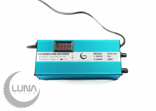
Also ordered the charger - totally adjustable, with read out
 lunacycle.com
As is with the 52V battery I've been hitting 22 mph on my display (23 or 24 on GPS) when over 60% charged. With the large chainring, I can still pedal at 21 or 22 with a cadence of about 70 (I think extends battery vs improves speed). All improvements beyond this point will not be pedallable (by me anyway). My pre-order features a 1000 watt motor, and a better cog / chainring combination (11-32 & 52) that should allow me to pedal at up to 28 to 30.
Julet Yellow to Red Connector Converter
Distributors and builders of life changing high power electric bikes.
lunacycle.com
Also ordered the charger - totally adjustable, with read out
Luna Charger 48V Advanced 300W Ebike Charger
Luna Charger 48V Advanced smart charger has different settings to prolong ebike battery life and charge batteries as fast as possible.
lunacycle.com
As is with the 52V battery I've been hitting 22 mph on my display (23 or 24 on GPS) when over 60% charged. With the large chainring, I can still pedal at 21 or 22 with a cadence of about 70 (I think extends battery vs improves speed). All improvements beyond this point will not be pedallable (by me anyway). My pre-order features a 1000 watt motor, and a better cog / chainring combination (11-32 & 52) that should allow me to pedal at up to 28 to 30.
Last edited:
Bravesst
Active Member
I've learned a lot, and for that I'm forever grateful, but sadly still no actual upgrades - except the 52 volt battery giving me about 2 or 3 mph, (maybe up to 4 fully charged). There seems to be issue after issue due to my lack of experience and Addmotor's selection of proprietary parts / programming.
Somehow, while I thought the motor connector fit, it does not. It looks like it will with the 3 hole / prongs, but I worked on it several times, for quite a while, and I'm not sure how I ever thought this issue was resolved, but it clearly is not. I was all set to do a dry run with new controller after all parts arrived.
Brake issue should be pretty basic, Luna sells a converter cable which I purchased 2 of, but until I get past the motor connector issue, I'm back to square one. Possibly the 3rd wire is for hydraulic brakes. I'm pretty sure throttle will not be an issue, and PA will be a matter of just plugging in. The display doesn't register speed, and I know it needs some kind of external sensor, even though I'm not sure why one display works, while this one doesn't.
Speaking of displays. My display, SW900 is supposed to 15 adjustable settings, mine has 4. All new SW900's that I find do not have the Julet / Higo plugs, rather this connector (exactly my display with the Addmotor logo).
https://www.amazon.com/gp/product/B07LBZ6KFN/ref=ox_sc_act_title_2?smid=A18NQE175QQAZM&psc=1
Would a simple display change enable me to reprogram the current controller to give me that 5 mph that I now so desperately need - just on the principle of hours / money invested?
I have a 1000 watt, fully programmable, Rize Blade on order for next month, and will inevitably sell this bike. I still do not want to be *defeated* by this project!
Any help or advice would be greatly appreciated,
MS
Last edited:
AHicks
Well-Known Member
- Region
- USA
- City
- Snow Bird - Summer S.E. Michigan, Winter Gulf Coast North Central Fl.
I wish I had known you didn't own a multi meter going into this, and were looking for something that would allow plug and play. I would NEVER have suggested or recommended this upgrade.
When you said you could solder, I assumed you were willing and able to do the homework required to match plugs as required. There is very little doubt that's what it's going to take to get the job done here. My apologies if I came across differently. -Al
When you said you could solder, I assumed you were willing and able to do the homework required to match plugs as required. There is very little doubt that's what it's going to take to get the job done here. My apologies if I came across differently. -Al
Mike_V
Well-Known Member
Hmm ...

Zippy performance, easy riding.
You do have the 750W Fat Tire Bafang motor because ( it's marked ) & the torque is evident, which is better than any 250 300 or 500 from s.o.b.
You will not reach any higher speed than when you lift the wheel and spin freely ~ 21MPH
That's it.
You will go uphill and down all day without overheating, it's a 750.
Bravesst
Active Member
No worries, this is a learning experience, and I do have a multimeter now. I can solder, usually working with 18 gauge wire and circuit boards. I am also beginning to wrap my head around the entire process, and what's needed. Working with these connectors is new, but I will master it. If I had the spare cable to splice in, I'd give it a try today, but I'm not gonna wreck my current controller.
Controller, 9 wire cable to motor - 3 large, 6 small

Current motor plug, 9 pins
.jpg")
Just for reference, the old controller plug that will have to be soldered into new controller. I know there's a link in here somewhere from
@harryS for a right connector

@Mike_V Not sure you're correct here, maybe. Current display allows a 40 KPH setting, and I think I'm hitting that. Wheel off the ground I can get 22 mph. Top speed measured by my GPS on flat ground is more 24+ when 52 volt battery is fully charged. (Seems like display is off about 1.5 to 2 mph). I've even seen 26 (on GPS) but with some wind, downhill hill, lots of leg power (via 60 tooth chainring), or all three.
Controller, 9 wire cable to motor - 3 large, 6 small
Current motor plug, 9 pins
Just for reference, the old controller plug that will have to be soldered into new controller. I know there's a link in here somewhere from
@harryS for a right connector
@Mike_V Not sure you're correct here, maybe. Current display allows a 40 KPH setting, and I think I'm hitting that. Wheel off the ground I can get 22 mph. Top speed measured by my GPS on flat ground is more 24+ when 52 volt battery is fully charged. (Seems like display is off about 1.5 to 2 mph). I've even seen 26 (on GPS) but with some wind, downhill hill, lots of leg power (via 60 tooth chainring), or all three.
Last edited:
Bravesst
Active Member
Just to mention, my motor cable is about 8 inches long. There is an approximate 2 foot extension cable from the motor cable to the controller. That gives me an extra connector. The big risk here is separating the connector from the cable on OLD controller and not being able to get the NEW controller to work - for whatever reason. I'm pretty sure I could reattach the cable, but now at least I can do it without disabling the OLD controller (just an extension cable).
In the end, the extension cable is just as important, but just easier to replace.
750 watt bafang motor ext cable
In the end, the extension cable is just as important, but just easier to replace.
750 watt bafang motor ext cable
Last edited:
Similar threads
- Replies
- 0
- Views
- 8K
- Replies
- 3
- Views
- 6K
- Replies
- 12
- Views
- 15K
- Replies
- 6
- Views
- 5K
- Replies
- 1
- Views
- 2K