AHicks
Well-Known Member
- Region
- USA
- City
- Snow Bird - Summer S.E. Michigan, Winter Gulf Coast North Central Fl.
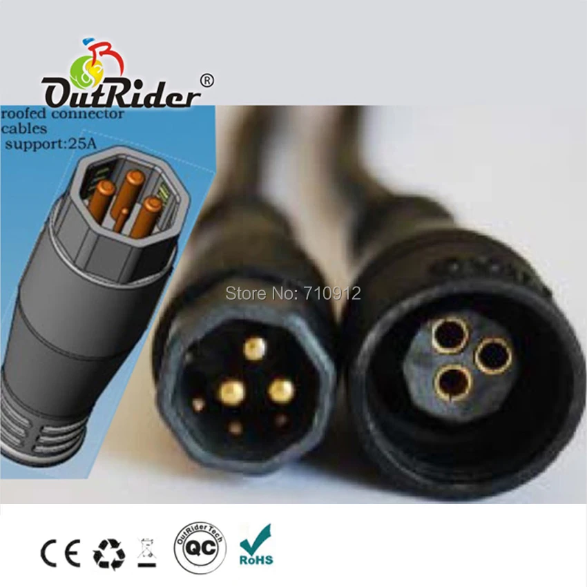
I don't have anything but the blurry pictures you've posted to go on, but it looks like there are 6 notches arranged around the outside of the main 3 wires on the one side. All but impossible to tell, is if those "notches" line up with the small pins on the other side?
Regarding matching the new vs. old wires, are you considering wire splices, or soldering a new pigtail on to your controller board? If planning a board level mod, I would highly discourage that.
Regarding matching the new vs. old wires, are you considering wire splices, or soldering a new pigtail on to your controller board? If planning a board level mod, I would highly discourage that.