Single Gear Stealth Build - Battery in Frame Tubes

LawrenceEaden

New Member
Hi All.

I'm a little way into my build now and I thought I would share my experiences. My main goal for the project is to build an eBike that doesn't look like one. I recently got a single gear bike to try because i like the aesthetic and simplicity. A bike like this has a compromise with the gearing though, you can choose to make it easy to take off at the lights and get up hills, or have a good top speed.

This lead to my eBike project, could i gear the bike for a good top speed pedalling, then have electric assist for hills and getting off the line.

The Bike
This is the bike I'm starting with from Hackney Cycles, London. (£160)
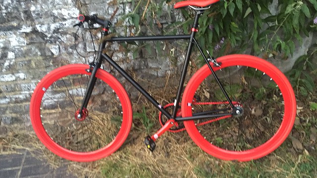
29744284290_d0bb0c6792_z.jpg


All the components feel extremely cheap but considering what i had planned for it I wanted to keep the risk capital low and I can always upgrade components later.

The Battery
This is where it starts to get a bit tricky. I don't want a visible battery on the frame, so i had the idea of putting the battery IN the frame using 18560 cells. I could only fit 20 cells in the frame (top tube 6, seat tube 6, bottom tube 8). This would let me do a 36v (10s,2p) battery. So I did some maths.

samsung-26f-18650-pair.jpg

Cells Used - Samsung ICR18650-26F (£3.95 each)
(Link Removed - No Longer Exists)

Weight
20 x 45g = 900g

Voltage
3.7 x 10 = 37V

Capacity
2.6Ah x 2 = 5.2Ah

Max Current Draw
5.2A x 2 = 10.4A

Max Power
37 x 10.4 = Approx 350w

WattHours
37V x 5.2Ah = 192.4Wh

I was then trying to work out what range this would give me i found lots of different estimations of how many WattHours per Mile you use, between 5 and 20. So I took the top estimate to be conservative.

Range
192.4Wh / 20Wh/m = 9.62 Miles

For a first build I think this will be okay. My commute to work is 7 miles, so i can charge at both ends, and it's fine to get to the shops and back. I always have the option for longer journeys to add another battery in parallel in a rucksack.

10s is quite a common setup so findng a BMS PCB is very easy. I will add the balancing wires when I build my pack.

The Motor

The maximum power my internal battery could provide is 350w so that's a good start for my motor spec. I wanted to keep the rim that came with the bike for the oem look. The rim has 32 spokes, most hub motors are made for mountain bikes which have 36 spokes, and 135mm drop outs.
(Link Removed - No Longer Exists)
The options were very limited so I went for the Q100C CST 36V350W (£117.88 inc shipping)
https://bmsbattery.com/ebike-kit/65...driving-hub-motor-ebike-kit.html#/213-rpm-201

I am waiting for this to arrive. but I have tried to work out the spoke configuration using a great online calculator here. http://www.ebikes.ca/tools/spoke-calc.html

The Controller

I have done a few home automation projects before using raspberry pis and arduinos so I would like to go down this route eventually to add my own features like gps and data logging. There are so many cheap controllers around though I wanted to get one to reverse engineer the circuit and use it to get the bike going.

61McIS69quL._SL1201_.jpg

I went for this one on amazon (£15)
https://www.amazon.co.uk/dp/B00EB84L70

I'm still not sure where to package this on the bike. I have seen you can get nice leather frame bags for tool kits. This could work well because it butts up to the frame so wires can go between them discretely and it's something seen on non electric bikes.

Power Control


For simplicity to start the power will be completely controlled by a thumb throttle.
s-l1600.jpg

I found an inconspicuous one on ebay. (£8.99)
(Link Removed - No Longer Exists)

Final Specs

Voltage
36v

Power
350w

Range
9.5 Miles

Weight
Motor = 2.1kg
Battery = 0.9kg
Controller + Wiring + BMS = 0.8kg approx
Total = 3.8kg

Battery Build

Finally I get to start making things! I have seen a lot of people build battery packs spot welding nickel strips to the cells, but because mine has to take on the form of a tube, i thought that soldering wires should be okay. I used 0.75mm2 wire for the parallel connections and 1.5mm2 for the series ones. The balance wires are rated to 2 amps, i only expect to charge at 1amp.

30037943285_8cbf524286_z.jpg


To fit in the tubes I am building 3 packs which will be joined in series.
Top Tube - 3s,2p
Seat Tube - 3s,2p
Bottom Tube - 4s,2p

I started by making the 10 parallel pairs
29409991174_79e258128c_z.jpg


Then linked 3 pairs together to make by first pack, and added wires for the balance charging. I tried to keep a 5mm gap between all the cells, and insulated all the ends with electrical tape to stop any shorts.
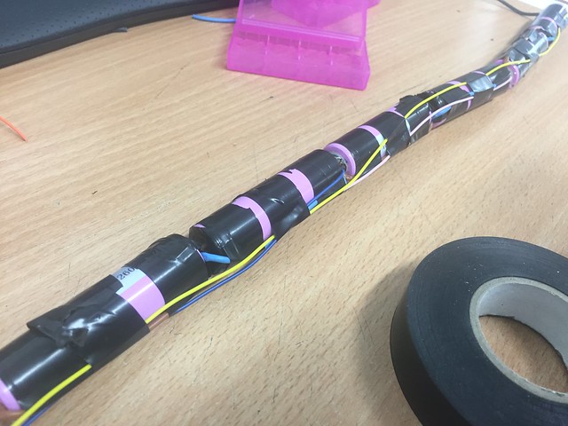
29409997244_f790b6f6ef_z.jpg


Once it was done i put heat shrink on it for a little rigidity and insulation. Two finished with ample wire at each end to route in the frame and add connectors.
29743967640_965888086f_z.jpg


This is as far as I'm up to with the battery. I have ordered more cells to finish the final pack. I am concerned about my soldering cracking after some time, so I think I will get some 20mm ID tube cut it into quarters down its length and heat shrink it to the packs for extra rigidity.

Frame Modifications

Okay so you may be wondering how i'm going to get these battery packs in the frame? I had a couple of options. The seat tube is easy, you can slide it right in but i can't get to the top or bottom tubes without drilling somewhere. a scary thought! I originally considered the bottom bracket after reading how over-engineered they usually are. but to get the right angle of hole i would come in contact with some welds for the drop out arms. So! Both holes could go through the head tube. I found some cool looking FEA for a bike frame and it looked like very little force went through the front face of the head tube.
FEA%20gif.gif


Drilling a 15degree and 30degree 25mm hole in the centre of a tube freestyle didn't sound appealing at first, I designed some sheet metal jigs that would give me the angle and position i wanted. But with a 10 day lead time and extra cost I scrapped that and made paper templates i could stick to the tube and drill up to the line.
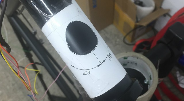
29924705232_b35fb11615_z.jpg


I got the angle grinder out to try and make a flat surface on the tube perpendicular to the tube the battery was going in. then centre punched and drilled a 5mm hole. I widened this with a stepper drill bit. finishing off with a die grinder to get the right profile.

30004368426_0831dc2821_z.jpg


I've only done one of the holes so far, but i'm pretty happy with the result! I removed the smallest amount of material to get the holes lines up to get the pack in the tube. I haven't done much modification work like this before, so i'm still learning the best ways to do things like this.
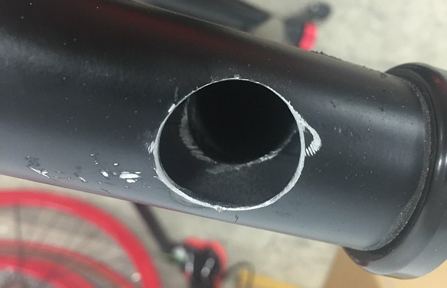
29410550194_b2a8ab3ccf_z.jpg


The pack fits! I haven't been able to find anywhere online someone making a DIY eBike like this so I'm going a little blind, but that makes it more fun as well! I will be left with two holes once i'm done, this could be perfect for designing a little custom front light and horn?


What's Next?

There's still a lot to do on this project, but as it's getting dark earlier now I have more motivation to stay after work and crack on with it. My list at the moment is

Bottom tube battery pack
Final wiring diagram
controller/bms packaging design
hub motor lacing to the hub when it arrives

Any comments, especially if you've seen any huge errors!, would be appreciated.

Thanks,
Lawrence.


I would try to run tests on the batteries. Find an electrical load of say 4 amps at the right voltage, and see how the battery works. You can run into issues where some wire paths are shorter, so less resistance, or even some of the solder joins may be better than others. You want to check that no cell is running down and getting below the safe level, around 3 volts. Plus you want all the cells at about the same voltage as they draw down.

I think you chose the steel frame. I would not know how to engineer those cuts, but steel is more like to bend a bit before it gives way.

Hope it all works out. Given the size of the controller I might have just chucked the battery pack in a little frame bag, handlebar bag, or seat bag.

It seems like when you build anything the first one is a massive learning experience. I don't know anyone who has been quite as ambitious as you have. So anything you can tell us is likely to be helpful to others, down the line.
 
Hi All.

I'm a little way into my build now and I thought I would share my experiences. My main goal for the project is to build an eBike that doesn't look like one. I recently got a single gear bike to try because i like the aesthetic and simplicity. A bike like this has a compromise with the gearing though, you can choose to make it easy to take off at the lights and get up hills, or have a good top speed.

This lead to my eBike project, could i gear the bike for a good top speed pedalling, then have electric assist for hills and getting off the line.

The Bike
This is the bike I'm starting with from Hackney Cycles, London. (£160)

29744284290_d0bb0c6792_z.jpg


All the components feel extremely cheap but considering what i had planned for it I wanted to keep the risk capital low and I can always upgrade components later.

The Battery
This is where it starts to get a bit tricky. I don't want a visible battery on the frame, so i had the idea of putting the battery IN the frame using 18560 cells. I could only fit 20 cells in the frame (top tube 6, seat tube 6, bottom tube 8). This would let me do a 36v (10s,2p) battery. So I did some maths.

samsung-26f-18650-pair.jpg

Cells Used - Samsung ICR18650-26F (£3.95 each)
(Link Removed - No Longer Exists)

Weight
20 x 45g = 900g

Voltage
3.7 x 10 = 37V

Capacity
2.6Ah x 2 = 5.2Ah

Max Current Draw
5.2A x 2 = 10.4A

Max Power
37 x 10.4 = Approx 350w

WattHours
37V x 5.2Ah = 192.4Wh

I was then trying to work out what range this would give me i found lots of different estimations of how many WattHours per Mile you use, between 5 and 20. So I took the top estimate to be conservative.

Range
192.4Wh / 20Wh/m = 9.62 Miles

For a first build I think this will be okay. My commute to work is 7 miles, so i can charge at both ends, and it's fine to get to the shops and back. I always have the option for longer journeys to add another battery in parallel in a rucksack.

10s is quite a common setup so findng a BMS PCB is very easy. I will add the balancing wires when I build my pack.

The Motor

The maximum power my internal battery could provide is 350w so that's a good start for my motor spec. I wanted to keep the rim that came with the bike for the oem look. The rim has 32 spokes, most hub motors are made for mountain bikes which have 36 spokes, and 135mm drop outs.
(Link Removed - No Longer Exists)
The options were very limited so I went for the Q100C CST 36V350W (£117.88 inc shipping)
https://bmsbattery.com/ebike-kit/65...driving-hub-motor-ebike-kit.html#/213-rpm-201

I am waiting for this to arrive. but I have tried to work out the spoke configuration using a great online calculator here. http://www.ebikes.ca/tools/spoke-calc.html

The Controller

I have done a few home automation projects before using raspberry pis and arduinos so I would like to go down this route eventually to add my own features like gps and data logging. There are so many cheap controllers around though I wanted to get one to reverse engineer the circuit and use it to get the bike going.

61McIS69quL._SL1201_.jpg

I went for this one on amazon (£15)
https://www.amazon.co.uk/dp/B00EB84L70

I'm still not sure where to package this on the bike. I have seen you can get nice leather frame bags for tool kits. This could work well because it butts up to the frame so wires can go between them discretely and it's something seen on non electric bikes.

Power Control


For simplicity to start the power will be completely controlled by a thumb throttle.
s-l1600.jpg

I found an inconspicuous one on ebay. (£8.99)
(Link Removed - No Longer Exists)

Final Specs

Voltage
36v

Power
350w

Range
9.5 Miles

Weight
Motor = 2.1kg
Battery = 0.9kg
Controller + Wiring + BMS = 0.8kg approx
Total = 3.8kg

Battery Build

Finally I get to start making things! I have seen a lot of people build battery packs spot welding nickel strips to the cells, but because mine has to take on the form of a tube, i thought that soldering wires should be okay. I used 0.75mm2 wire for the parallel connections and 1.5mm2 for the series ones. The balance wires are rated to 2 amps, i only expect to charge at 1amp.

30037943285_8cbf524286_z.jpg


To fit in the tubes I am building 3 packs which will be joined in series.
Top Tube - 3s,2p
Seat Tube - 3s,2p
Bottom Tube - 4s,2p

I started by making the 10 parallel pairs
29409991174_79e258128c_z.jpg


Then linked 3 pairs together to make by first pack, and added wires for the balance charging. I tried to keep a 5mm gap between all the cells, and insulated all the ends with electrical tape to stop any shorts.
29409997244_f790b6f6ef_z.jpg


Once it was done i put heat shrink on it for a little rigidity and insulation. Two finished with ample wire at each end to route in the frame and add connectors.
29743967640_965888086f_z.jpg


This is as far as I'm up to with the battery. I have ordered more cells to finish the final pack. I am concerned about my soldering cracking after some time, so I think I will get some 20mm ID tube cut it into quarters down its length and heat shrink it to the packs for extra rigidity.

Frame Modifications

Okay so you may be wondering how i'm going to get these battery packs in the frame? I had a couple of options. The seat tube is easy, you can slide it right in but i can't get to the top or bottom tubes without drilling somewhere. a scary thought! I originally considered the bottom bracket after reading how over-engineered they usually are. but to get the right angle of hole i would come in contact with some welds for the drop out arms. So! Both holes could go through the head tube. I found some cool looking FEA for a bike frame and it looked like very little force went through the front face of the head tube.
FEA%20gif.gif


Drilling a 15degree and 30degree 25mm hole in the centre of a tube freestyle didn't sound appealing at first, I designed some sheet metal jigs that would give me the angle and position i wanted. But with a 10 day lead time and extra cost I scrapped that and made paper templates i could stick to the tube and drill up to the line.

29924705232_b35fb11615_z.jpg


I got the angle grinder out to try and make a flat surface on the tube perpendicular to the tube the battery was going in. then centre punched and drilled a 5mm hole. I widened this with a stepper drill bit. finishing off with a die grinder to get the right profile.

30004368426_0831dc2821_z.jpg


I've only done one of the holes so far, but i'm pretty happy with the result! I removed the smallest amount of material to get the holes lines up to get the pack in the tube. I haven't done much modification work like this before, so i'm still learning the best ways to do things like this.

29410550194_b2a8ab3ccf_z.jpg


The pack fits! I haven't been able to find anywhere online someone making a DIY eBike like this so I'm going a little blind, but that makes it more fun as well! I will be left with two holes once i'm done, this could be perfect for designing a little custom front light and horn?


What's Next?

There's still a lot to do on this project, but as it's getting dark earlier now I have more motivation to stay after work and crack on with it. My list at the moment is

Bottom tube battery pack
Final wiring diagram
controller/bms packaging design
hub motor lacing to the hub when it arrives

Any comments, especially if you've seen any huge errors!, would be appreciated.

Thanks,
Lawrence.


Nice build, Lawrence! If I may ask, why did you decide to go with the 26F cell when there are other cells out there that offer higher energy density and higher current draw at a similar price? For instance, the Panasonic NCR18650PF cell offers 10A max current draw and 2900mAh and is a mid-priced cell ($2.00-$2.50/cell in bulk, shipping not included).
 
Last edited:
Wow! I'm following this thread.
Thanks!

I would try to run tests on the batteries. Find an electrical load of say 4 amps at the right voltage, and see how the battery works. You can run into issues where some wire paths are shorter, so less resistance, or even some of the solder joins may be better than others. You want to check that no cell is running down and getting below the safe level, around 3 volts. Plus you want all the cells at about the same voltage as they draw down.

I think you chose the steel frame. I would not know how to engineer those cuts, but steel is more like to bend a bit before it gives way.

Hope it all works out. Given the size of the controller I might have just chucked the battery pack in a little frame bag, handlebar bag, or seat bag.

It seems like when you build anything the first one is a massive learning experience. I don't know anyone who has been quite as ambitious as you have. So anything you can tell us is likely to be helpful to others, down the line.

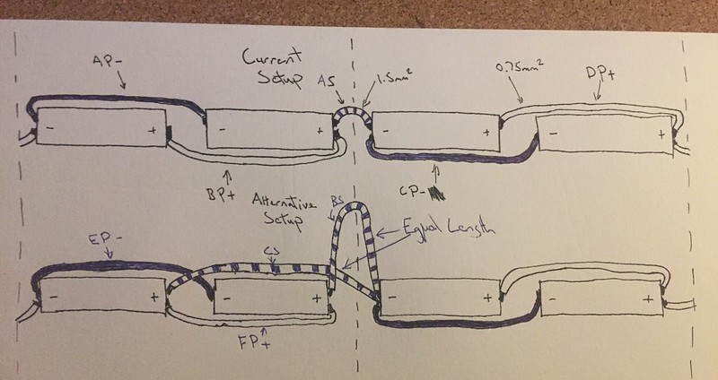
Ah. The Battery is one of the aspects that I think will need ongoing development. I was planning on checking the voltages on each of the balancing wires in the pack before charging to see if it was drastically unbalanced. From what I have read there shouldn't be any issues with any of the parallel pairs because they balance each other. I've done a quick sketch of my current pack wiring set up and how I could make the wires more equal length.
30038293286_75292f09ef_c.jpg

Would adding extra series wires help? I don't know if that is a bit over the top. I think it will be easier to see once I can test.

It is a bit risky drilling the frame, I'm hoping that if i keep the holes at the front no larger than the ID diameter of the tubes it shouldn't be catastrophic. I may try and find a way to reinforce it. Perhaps a plate to screw into the front.

This controller is hopefully only temporary. I would like to design one to fit in the void under the seat. Or if i do put it in a frame bag i'd like to keep it as small as possible. A battery in a bag would have been a simpler route but I wanted to try this because I haven't seen anyone else do it. There may be a reason for that though..

Thanks for your comments George.

Nice build, Lawrence! If I may ask, why did you decide to go with the 26F cell when there are other cells out there that offer higher energy density and higher current draw at a similar price? For instance, the Panasonic NCR18650PF cell offers 10A max current draw and 2900mAh and is a mid-priced cell ($2.00-$2.50/cell in bulk, shipping not included).

You're right Cameron. They would have been a better choice. A guy at work already had 6 of these cells he was going to use for another project but never got round to it, so I already had 30% of my battery for free, and I was able to find a UK supplier incase i killed any cells I wouldn't be waiting for chinese shipping to get more. I've seen it done elsewhere but I didn't want to mix different cell types. I haven't seen them at that price, I'm not sure 20 cells counts as bulk. Have you used these? Do they perform well?
 
I would try to make a 36 volt load that draws a few amps. We can get cheap 12v DC bulbs in the US, like tail light bulbs, the incandescent kind. You need holders for most bulbs.

These are cheap 12v DC lights with standard screw in mounts. These draw about 4 amps, so three in series to make a 36 volt load.

All you can do is charge and discharge the pack to try to check the connections and individual cells.

Overview here. Most designs favor very short connections distances.

Very, very long thread on DIY HERE.
 
A lot of that controller is air and wires inside, and connectors outside, and you probably don't need all the options provided by the connectors. If you get rid of the case, remove the wires you are not going to use, use either direct wirin or small connectors, and add a heat sink for the transistors, you could probably fit it into a slot on a luggage rack, with appropriate weather sealing.
 
I would try to make a 36 volt load that draws a few amps. We can get cheap 12v DC bulbs in the US, like tail light bulbs, the incandescent kind. You need holders for most bulbs.

These are cheap 12v DC lights with standard screw in mounts. These draw about 4 amps, so three in series to make a 36 volt load.

All you can do is charge and discharge the pack to try to check the connections and individual cells.

Overview here. Most designs favor very short connections distances.

Very, very long thread on DIY HERE.

Great Info! Thanks. I'll update once I've done my tests with the complete pack.


A lot of that controller is air and wires inside, and connectors outside, and you probably don't need all the options provided by the connectors. If you get rid of the case, remove the wires you are not going to use, use either direct wirin or small connectors, and add a heat sink for the transistors, you could probably fit it into a slot on a luggage rack, with appropriate weather sealing.

I am planning to take this apart to get the tightest packaging I can. I keep minimal wiring on the outside of the frame and a more discrete look I want to use a leather frame bag like the one below.
2df2edb1ab4e16d88dc3800795568fef.jpg

Adding a rack would be unsightly. I can make my own one to fit snug around the components, and even have a key ignition switch on one face for a little security. I've ordered this one from ebay (£2.25)
(Link Removed - No Longer Exists)
s-l1600.jpg


Then under a flap I'm planning on having a combo V/A meter. This will be my main way of seeing how much range i have left. Something similar to this.
(Link Removed - No Longer Exists)
ZC15400-C-3-1.jpg

I don't want anything else on the handlebars, so under a flap maybe held down with a magnet that i can flick up at traffic lights should be ideal.
 
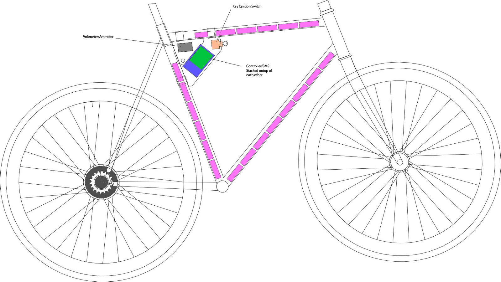
I drew up in CAD a 2d model of the packaging of the components, it may help you understand the project a little better.

30031791811_e1d6a187e3_h.jpg


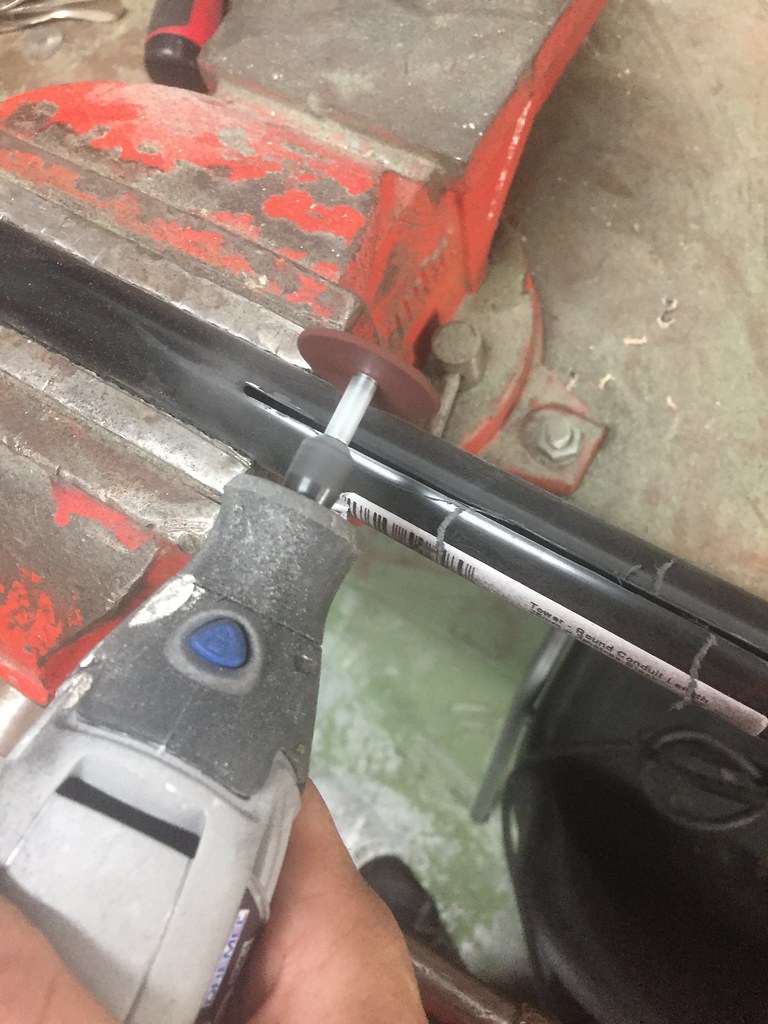
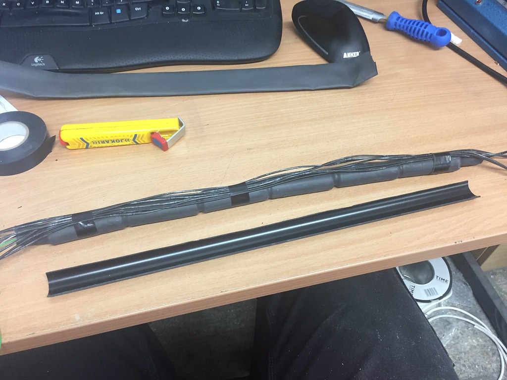
I have also done as I said and found some conduit pipe with the OD just smaller than the ID of the frame tubes.
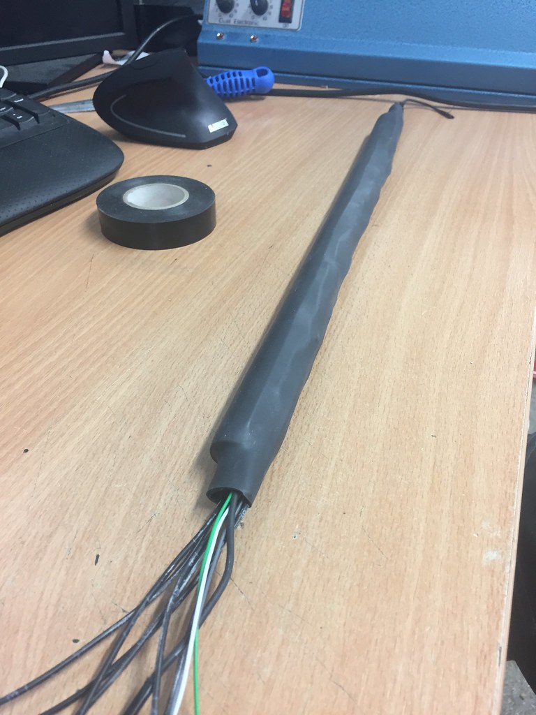
I added some a few more wires down the pack as redundancy incase i wanted to add a pedal assist sensor later and heat shrinked/shrank(?) a section of the pipe to the pack. It's starting to look a bit more like a battery now. I need to find some good connectors to go on the ends.

29503719544_9a74a2623f_b.jpg

Cutting the Conduit with a dremel

30017575902_cc94c37850_b.jpg

Wires taped to the batteries

29503719764_be350d05c6_b.jpg

One pack finished with reinforcement.

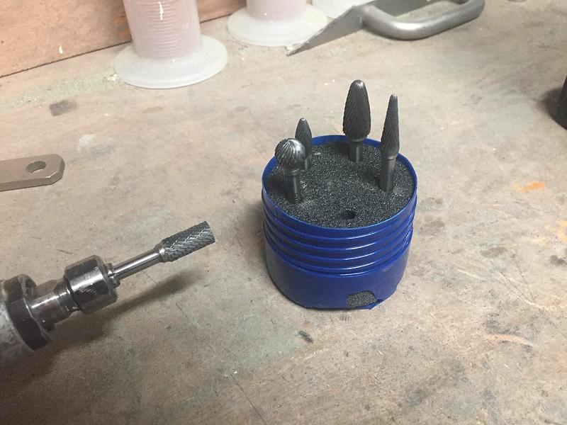
Some Carbide die cutter bits came today to make the second head tube hole easier to do hopefully.
 
Frame Modifications - Second Head Tube Hole

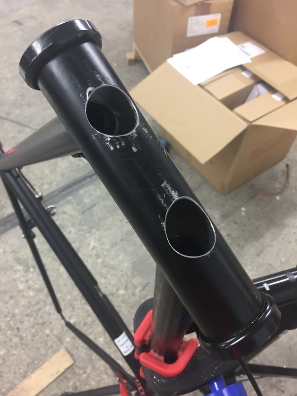
I got some carbide die cutter bits this week to make the second head tube hole a bit easier than the first. It made such a difference with them actually cutting the metal instead of grinding it off with the stone bits.
29538521334_2d47a6190a_c.jpg


Both holes finished! The next frame modifications I need to make are a cable route through the bottom bracket between the seat and down tubes for battery cables. Also making slots in the seat and top tube where the controller bag will be for cables to go between there.
29538521024_3b82e7a04e_c.jpg


Controller Bag

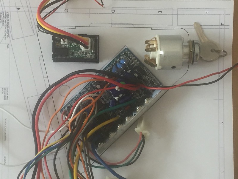
I'm trying to make the frame bag for the controller as small as I can. This is my first layout of the components to go in. I think i can tighten up some of the gaps and get a smaller ignition switch. For material I'm trying to get hold of a cheap leather jacket on ebay this weekend I can cut up, it may also have some useful clasps or zips on it.
30144473406_93b917599a_c.jpg
 
For material I'm trying to get hold of a cheap leather jacket on ebay this weekend I can cut up
Interesting ebike project. For leather consider Tandy. You can get heavy leather that will hold a shape better and probably cheaper than a jacket. Tandy also sells small bottles of finish, stitching and adhesive. Working leather isn't difficult, especially given the amount of other work you're doing with this build. Good luck!

https://www.tandyleather.eu/en/cate...5083e3b0e8efa4a39e73d723f5&remember_country=0
 
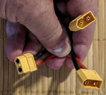
It's starting to look a bit more like a battery now. I need to find some good connectors to go on the ends.
The RC hobbyists worked up the XT60 connector and it has become a standard in much of the US DIY ebike industry. They are small but handle high currents.

Screenshot 2016-10-08 at 9.01.19 AM.png
 
@J.R. Thanks I had a look at their leather. It is more money than I'd like to spend, i got a second hand jacket on ebay.

@GeorgeS Those connectors look great! I need single wire connectors though like on the phase wire i think. my battery positive and negative will be in different frame tubes. Also i need to keep the bulk down. I believe the phase wire type connectors are waterproof with the heat shrink on.

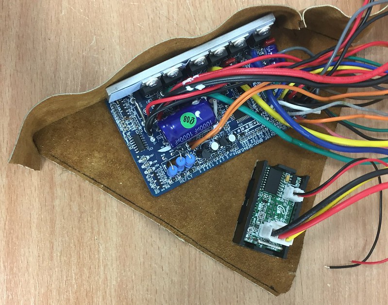
I was considering the controller heat sync and thought why not just modify the casing it came in.
29948978270_4353de1d6f_c.jpg


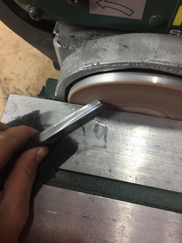
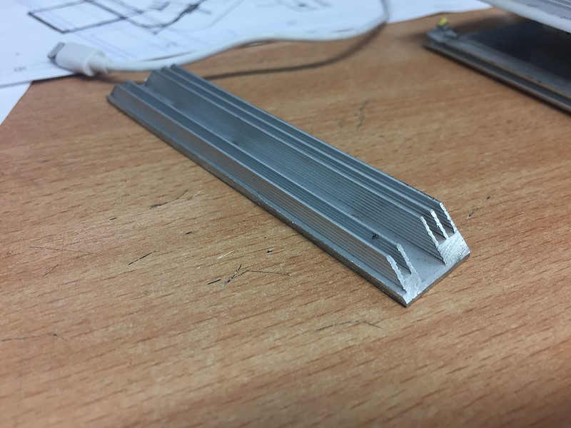
One side already has the holes to screw into the metal block the FETs are mounted to, so it's ideal and a quick job to cut and chamfer the ends to look a bit better when mounted on the outside of the frame bag.
29615775023_a063ec64a3_c.jpg


It's quite small, so I'm not sure how effective it will be, but the vanes will be positioned so lots of air should go over them as I ride.
30159936241_60e26f062f_c.jpg


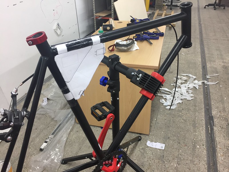
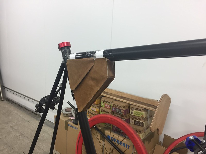
I've been revising the packaging of the frame bag to try and get it as small as I can. This is a template on the frame to help me understand how it's going to look.
30130370242_37040b0a89_c.jpg


I'm happy with the silhouette on the bike. I think even with the bag it should still be in the 'stealth' category. I've bought a second hand leather jacket on ebay (£9) to make the bag from, I am still on a budget making this.

s-l1600.jpg


The colour looked very similar to some leather seats and bar tape I've seen before, so i'm hoping I can get some that are close to matching. I'm now trying to choose the rest of the colour scheme. Currently a gunmetal frame with a dark rust colour for the wheels is prevailing. I may do a few photoshop renders to help decide.
 
@GeorgeS Those connectors look great! I need single wire connectors though like on the phase wire i think. my battery positive and negative will be in different frame tubes. Also i need to keep the bulk down. I believe the phase wire type connectors are waterproof with the heat shrink on.

Those are very elegant connectors. I've never run across them except on a controller and coming out of the motor. I mostly use the standard crimps which come in insulated and even in shrink wrap. I don't love crimp connections.

The good thing about heat sinks is that you can pretty much touch them and know if they are working. Some percentage of the power gets turned into heat but that's a pretty decent overall surface area with the fins.

Your ebike is coming together very nicely. I'm not patient enough to arrange all this stuff, and stealth is not too important for me. But this is impressive and I can see where you are going. There are people who want to have a refined look, and work at it. Eric offers suggestions for how to simplify the ebikes. It's hard to make the systems work really well, have the bike be very functional, and then make it completely stealth. When Eric says "Let's ban cruise controls" I'm like "What's it to you, if someone else wants to use one?" I like what you are doing. It's very unique. I hear designers get paid a lot more than mechanics. Most of what you are doing makes a lot of sense, just as a design.

Screenshot 2016-10-11 at 9.10.21 AM.png
 
Thanks for the kind words George. My background is in Industrial design so I do have a drive to get the little details right.

Frame Bag Mock Up

I picked up the leather jacket I'm going to use to make the frame bag yesterday and even though it's small, there's ample material. I managed to make an almost full mock up of the bag using only one sleeve!

30252430006_5a132cfebf_c.jpg


After making this mock up I think i'm going to have to make a few, most of the project is purely function with hidden form, but this bag is going to affect the aesthetic of the bike quite heavily. It's a small detail I really want to get right.

30287315405_d893003633_c.jpg


I've never worked with leather or many textiles before, but it's so thin it doesn't really affect the design of the bag at all. The mock up is only super glued together with a 3mm seam all round.

29656865173_76a0321d09_c.jpg


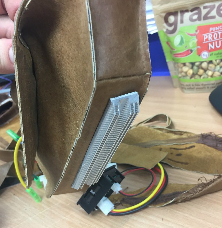
Getting to look at the heat sink on the bag is encouraging. I think I will paint it a rusty red colour, the same I have planned for the wheels. I've done a mockup of the colour scheme I'm after. Metallic Gun Metal frame and a deep rusty red for the wheels.

30288045995_a0a8ce5a4b_c.jpg


Motor Modifications

After making the mistake with the first motor I ordered of getting a 36 not 32 spoke hub I couldn't find a hub motor the right width, so I took a punt and got a 135mm wide motor hoping I could modify it to fit. It arrived today! I'm happy I made the swap, it's about half the weight of the 8fun one I started with. Apparently the same specs...

It came with a free hub to fit a cassette, I wasn't sure what fitting out be underneath, hoping it would be a male thread I could put the single gear freewheel that came with the bike on. Instead there was a female thread which I couldn't find any information on, i'm guessing these components are unique to hub motors? Has anyone had any experience with these?

29677122523_ae018965a9_c.jpg


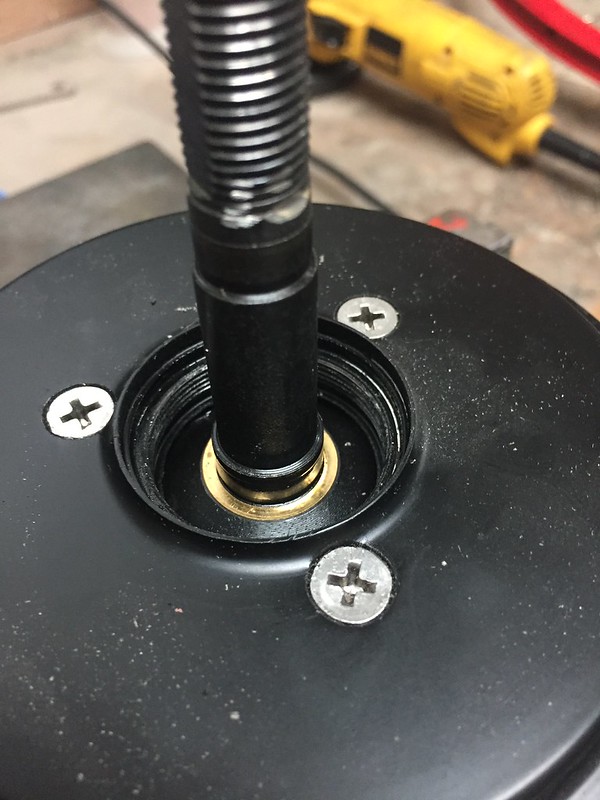
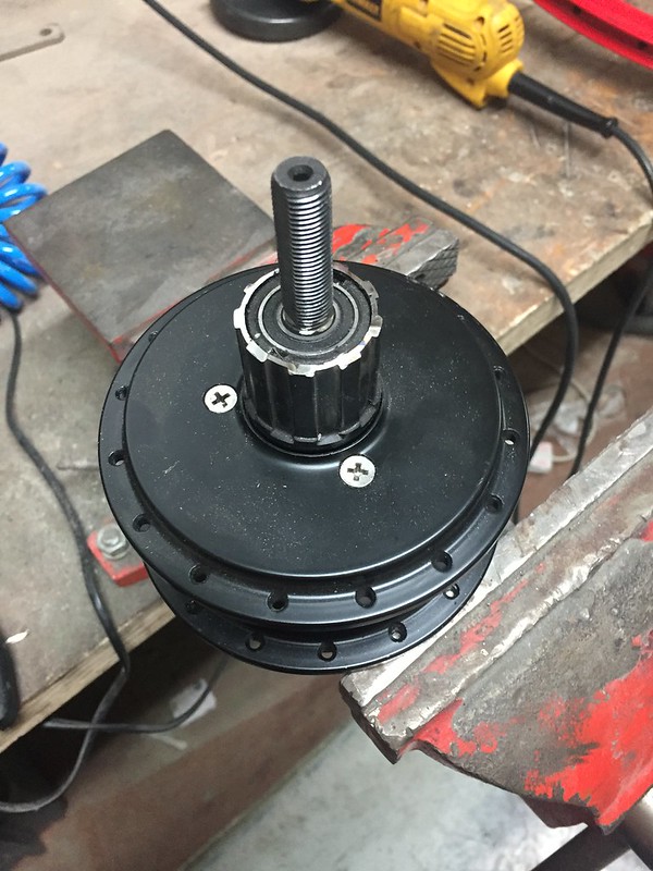
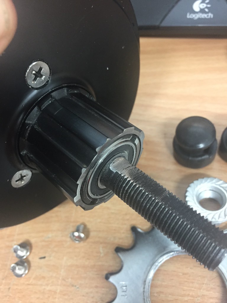
inspecting further I saw that the freewheel had two bearings that positioned on the shaft and secured it to the motor, which had to stay. So i cut it down as much as i could keeping this in tact.

30010886360_6ea8b7745d_c.jpg


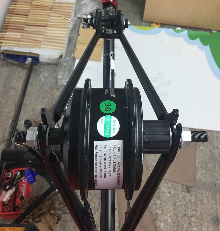
I then just had to file down the shaft a little to fit in the frame properly, i wasn't too worried about tolerances on this cut because the torque washers would still be seated on the original flat reducing any chance of movement under load.

30010887950_9717807d6b_b.jpg


This all worked out pretty well for centring the hub in the frame, i did a rough measure and found the centreline of the motor hub only to be 2mm offset from the frame centreline.

30221892271_0e5691ccdf_c.jpg


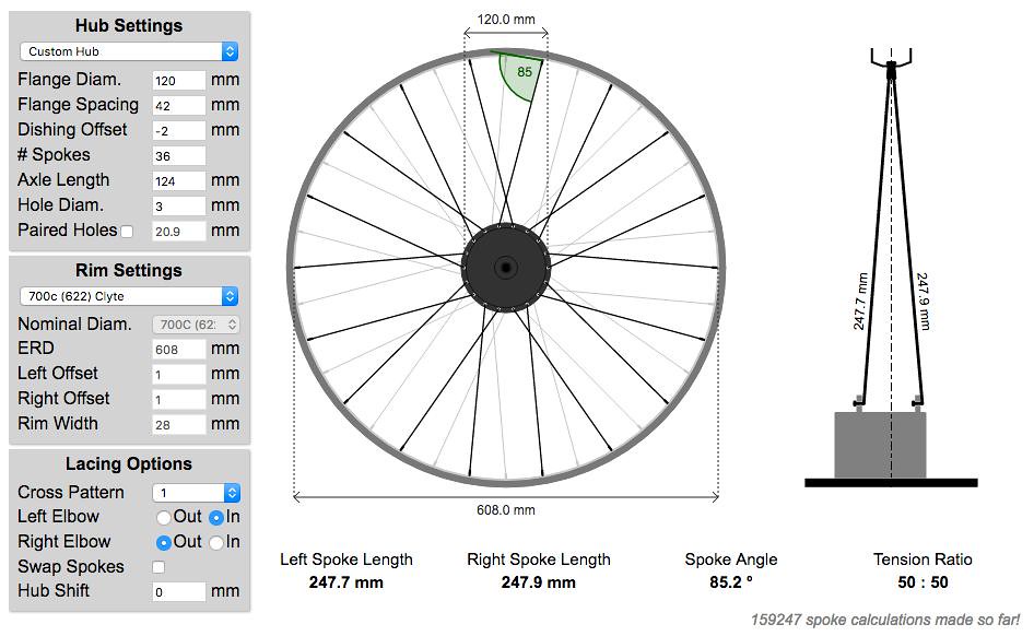
I checked this on the webpage i mentioned earlier for calculating spoke lengths on hub motors.
29677398883_1b5ba09eaf_b.jpg

http://www.ebikes.ca/tools/spoke-calc.html

Ta Dah! There is a bit of tolerance in my measurements, but it's come out at 50:50 tension. I don't know if there are any issues caused by putting the spokes right on the right hand side of the hub flanges.

I cut off the thread on the freewheel which usually holds the cassette on, my plan is to file a groove on the freewheel which i can put a circlip on. I can then position a single sprocket with spacers either side to get the chain line right, like a lot of single gear conversions I've seen.

I think I've now got everything I need to give the whole system a bench test, so that will be my next step early next week.
 
Controller Confusion

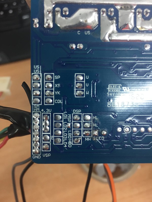
I've been trying to get my head around the controller. The wire colours appear to be completely different to what stated on amazon where I bought it. Some of the connections seem crazy to me! There's a two wire connector that is is 36v with no protection connecting to a rail which then makes a 36v live wire on another 3 wire connector.

I've taken it back to bare bones and I'm trying to identify the connections by the control boards annotations. So far I have the following


  • Hall Connections

    • U - Yellow Phase Wire

    • V - Green Phase Wire

    • W - Blue Phase Wire

    • GND - Ground

    • 4.3v - 4.3v supply


  • Unknown 3 Pin connector

    • HBD - Orange wire

    • LBD - Grey Wire

    • GND - Ground


  • Unknown 3 Pin connector

    • VSP - Pink wire

    • SP - Green Wire

    • GND - Ground


  • Unknown 2 Pin connector

    • DSP - Green wire

    • GND - Ground


  • Unknown 2 Pin connector

    • DSP - Green wire

    • GND - Ground


  • Unknown 2 Pin connector

    • D+ - Power + (Battery, 36v)

    • L - Orange Wire


  • Unknown 3 Pin connector

    • US - Green Wire (connected to the blue motor phase wire)

    • L - Orange Wire

    • YK - Brown Wire


  • Unknown 1 Pin connector

    • US - Blue Wire


  • Motor Phase Teach

    • 12/6 - White Wire

    • GND - White Wire


  • Unknown 1 Pin connector

    • HH - Purple Wire


  • Battery connector

    • D+ - Battery Positive

    • D- - Battery Negative


  • Charge connector..?

    • D+ - Battery Positive

    • D- - Battery Negative


  • Unknown 1 Pin connector

    • HL - White Wire
30319617841_dfcebee691_c.jpg


I don't really want to start connecting things up wildly. Any knowledge on this would be appreciated. I haven't been able to find any searching so far. The controller is a YK85s. I'm hoping that the board annotations are universal and someone can help.

Also I got to put my two motor options side by side and there's a huge difference between the Q100 and the 8fun for the same power rating.
30405696085_132c0b45a6_c.jpg


Thanks!
 
Controller Simplification

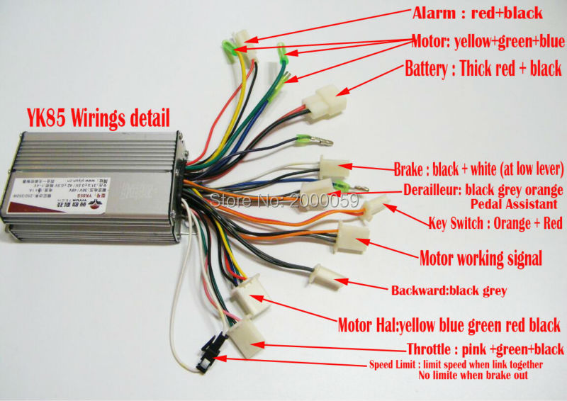
I managed to find another supplier of this controller, the YK85S (different to the YK85), to request an electrical diagram and got the following back.

HTB1NC46MpXXXXc3XVXXq6xXFXXXA.jpg


This let me cut back and insulate all the wires I don't need, everything but the key switch, battery, motor, motor hall and throttle wires. Leaving an annotation on the cut down wires incase I need them in the future. I'm leaving out the brake sensors for cutting the motor because I'm not using pedal assist and my throttle is a thumb throttle which I think is safer than a twist throttle, so my cut offs are no throttle, then the ignition key in the frame.

I got the motor spinning up and wanted to check a few voltages. The throttle output ranges between 0.8v and 3.5v output with a 5v input. This sounds like I can't get full throttle if the controller sees full throttle as a 5v input. One of the motor wires measured 18v at full throttle. I'm assuming this is meant to be the same voltage as the battery pack? (37v). I have yet to test putting 5v to the throttle and measure the motor voltage. If this is the case I'll make a simple summing op amp circuit with a potentiometer on one input and the throttle output on the other so I can easily tune it.

Wheel Building

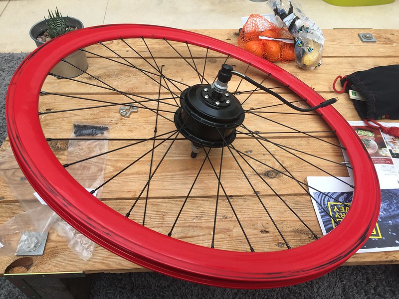
Lacing up the wheel is the last thing i have to do before i can do a test ride, so it's top priority. I'm planning on changing the colour of the rims, which I know would be easier with the wheel in pieces, but i want to get a proof of concept first before refining and polishing the details.

30449025306_9ea8da1fe6_c.jpg


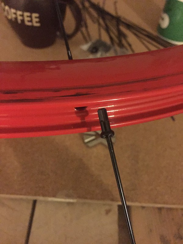
It's pretty simple and easy to lace up the wheel, the only tip i worked out was the only way to get the nipple through the double skin rim is to twist it on the end of a spare spoke and thread through the hole.

29853122243_2360962d19_c.jpg


Motor Optimisation

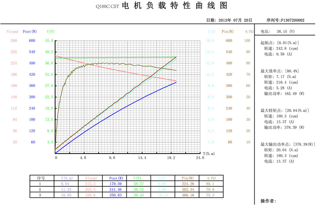
When trying to choose my motor I was susprised how little technical information was available for each brand. Luckily, the motor that I had to end up getting due to the 32 spoke pattern did have a torque curve document.

29855452924_aaa7d9d75d_b.jpg


I'm interested in the playoff of motor efficiency and torque. I'm hoping to be able to do some data logging at some point which I can map bag to this document to eventually create an hidden indicator of when I'm travelling at peak efficiency and peak torque or somewhere in the middle. None of this is really essential for the project, but it will be useful to understand for getting the most out of the bike.

I just found a very elegant build trying to achieve the similar kinds of stealth I'm after here https://endless-sphere.com/forums/viewtopic.php?f=6&t=64720
It's made me revisit my frame bag design, maybe even that may be too unsightly, I think i'll stick with it for now, then when I look at designing my own controller circuitry later down the line I want to explore the space under the seat, there could be enough of a void to keep it invisible from the side profile.
 
I think when you get the ebike, even the most basic version of it, completed, a few hundred miles of riding will clarify things. Things interact, and some things are just the way they are, the way the parts work. Some motors have internal controllers, which spares you grief and bulk. The Golden Motors come to mind.

That ES build is quite nice and there is very little to it. I looked at the parts on the BMS site and it is an $80 motor with a small controller that is designed to fit in a bottle type enclosure. He's using a couple of LiPo batteries which, again, are quite cheap. So, yeah, put the batteries and the controller in a bottle, put a basic throttle on it, and go. You have to just dive in and do what you can do. If you look at some of the Titan flight batteries, or LiPo batteries, you might find stuff you could hide.

You need to test your frame and you need to see if the battery works fairly well. The battery will limit how much power you are going to get. The LiPos in the other build will give you tons of power, but you'll run into other problems.

Power and torque will matter at the extremes. The question for most ebikes, the practical question, is whether it will climb a hill. How well the motor sheds heat affects efficiency. For the most part motors are about 80% efficient where they are used most of the time.

You can't learn it all on one build. It's a blend of parts as available and design, aesthetics. I like that ES build because the parts list is dirt cheap. I assume he is hiding a couple of these in the bottle, with the controller.
 
I have seen integrated motors and controllers, but I enjoy the modification and making my own things so I want to learn more about how it all works.

I've been looking at some of the other threads for stealth builds and I don't think I'm doing enough, I wondered if I could be rid of the frame bag completely, and the throttle. Could the only visible part of the build be the motor? I would have to displace all the components in the bag, the controller, key ignition, and battery indicator.

Redefining the Controller.

As I was reverse engineering the controller I realised how many functions on it are over spec'd and redundant on my build. If I wanted to only control the bike with a signal wire did I even need an eBike controller? I found another option on ebay that is far smaller.

s-l1600.jpg

(Link Removed - No Longer Exists) (£8.59)

This is a simple board for controlling a BLDC motor, I am going to get one to see if I can work out which component limits it to 36v and if a fully charged battery would burn it out at above that voltage (40v). It's a step towards designing my own board to integrate bms and motor control which is the plan down the line, but even with them as separate boards I'm getting into the realms of fitting them under the saddle in a 3d printed hard case. This could be completely invisible from the side, with a rear light covering it from the back. Exciting!

Ignition Switch

I am quite worried about security for the build as with anything you put work into. I saw a really cool GPS tracker that slots in the head tube (one of the few places I have left to put anything on the bike).

s-l1600.jpg

(Link Removed - No Longer Exists) (£28.97)

This can be armed and disarmed with an RFId tag, I'm hoping that I can find a part of this circuit that I can run a wire from out of the bottom of the fork back into the frame to my controller. This would let me switch between the gps tracker and alarm being live, or the motor being live with a quick tap. (Also super confusing for anyone trying to steal it).

Throttle

For simplification the project so far has worked around using a thumb throttle, which i think I will still use to start and get it going. I always thought that the cadence sensors wouldn't work for me because i want to use the electrical power from standstill. (I realised my build is the eBike equivilent of a koenigsegg regera in terms of power train if you count me as the ICE). I've learnt a lot about torque sensing bottom brackets and it sounds ideal, as i put all my weight on a pedal from standstill the motor will shoot me forward (hopefully).

TDCM_120.jpg

(Link Removed - No Longer Exists) (£118.57)

It's a bit more of an expensive option so it will probably be one of the last things on the project when I know the rest is working, but it would be the icing on the cake to have nothing extra on the handlebars. This torque sensor outputs a voltage between 2.4v and 3.4v. I would need to create a small board with some op amps to modify this to run with the other driver board if it works.

Battery Level Indicator

I can simply this to a LED bargraph somewhere on the bike, this is one thing that would be nice to have visible as I ride. Perhaps it could be recessed into the stem with a smoked polycarbonate cover, anything that doesn't look out of place when the bike is off. The control circuitry for this would be integrated in the same board I would make for the bottom bracket. I'm unsure whether to use a mirco - controller for these circuits or keep it as basic components and chips.

s-l400.jpg

(Link Removed - No Longer Exists)

I like that this one has a blue one on the end I could program to indicate charging.


This is a classic example of a project getting extended when not far from conclusion, but I think it's a good time to make the change, not too extreme and all still achievable. (lucky i hadn't cut the frame where the bag was going to go yet).

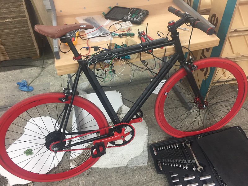
Tonight I've been truing the wheel and I'm tempted to zip tie everything to the outside of the bike and have a test ride.
 
Motor Burnout

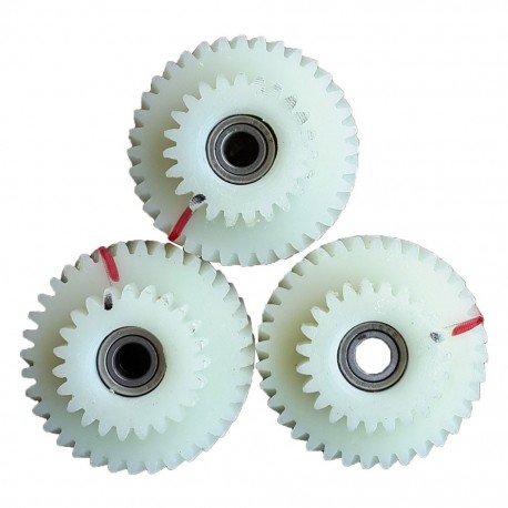
So i got everything together on the outside of the bike to give it a first test ride around the factory, it was working on the stand, all good. Then as the guys were playing with it, spinning up the back wheel with it off the ground they did a kind of burn out on the floor (motor at high rpm) for about 2 seconds then after I smelt a plastic/rubber smell. It wasn't until the evening when I wanted to have a go I noticed the motor was spinning in the casing but not turning the wheel, you could get it to turn sometimes, but not others, dependant on wheel start angle.

I'm assuming this means stripped gears inside. I know the motor isn't designed for doing what it did, but i expected a little durability. I've read other cases where people have done this on here, but that's usually when overpowering the motor, and then I've been unable to find replacement gears anywhere that will fit.

The closest I've found is on BMSBattery where I got the motor originally.
a-set-of-q100-gears-ebike-kit.jpg

https://bmsbattery.com/415-large_defaul ... ke-kit.jpg ($8.90)

But it says it will not fit my model (Q100C CST). Does anyone have any ideas? or is this a super expensive mistake and means a new hub motor? I'll disassemble the motor this week to find out more.

30627390356_32069b2b12_c.jpg


Frame Modifications

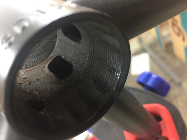
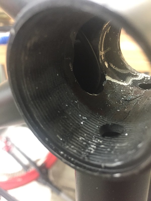
Because I hadn't taken chunks out of my frame for a few days I got the die grinder out again to work out the cable routes though the bottom bracket. This is how the frame started, I've noticed in all the tube welds there is a relief hole, i'm assuming this is for air flow during welding, or to purge the inside with flux.
30653515071_a938d739e0_z.jpg

2 minutes later with a carbide bit...
30106284053_caefed57ab_c.jpg

This cut is pretty rough but it was so difficult to keep the bit from biting and it will be hidden, I just need to smooth it out so wires don't snag.

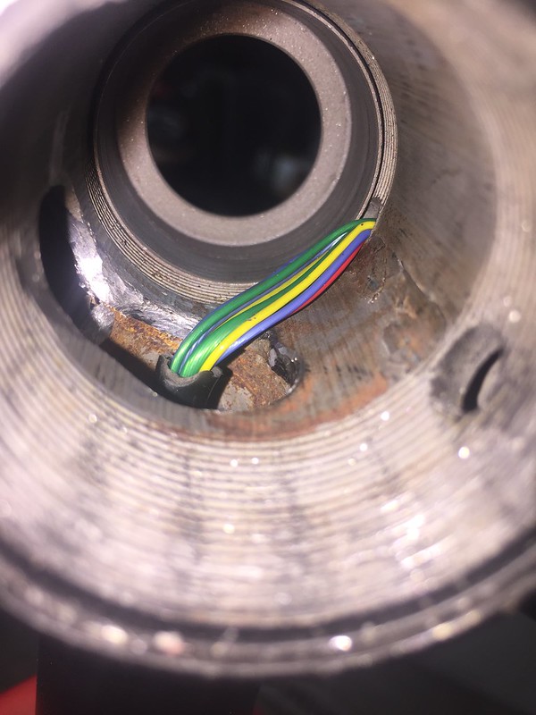
I want to try and get the motor cable to run mostly internally as well (inspired by seeing the hole in the photo above that goes to the rear drop arm).
30704340996_238936546e_c.jpg

If I strip off the outside sheath i can lay the wires flat to go around the bottom bracket without having to take any more material out. I just need to cut back about 5mm of thread off the bearing cup on the non drive side.

Motor Modifications

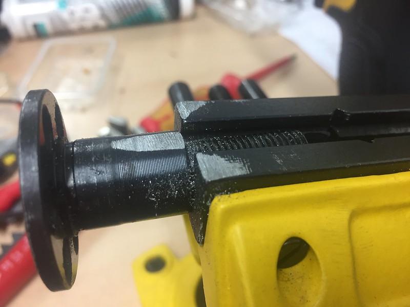
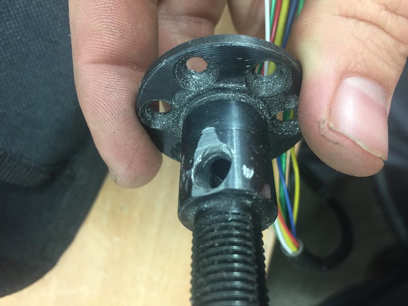
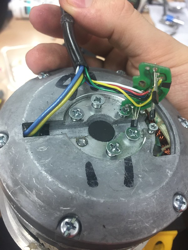
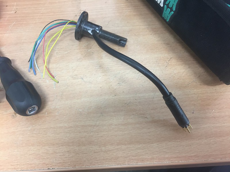
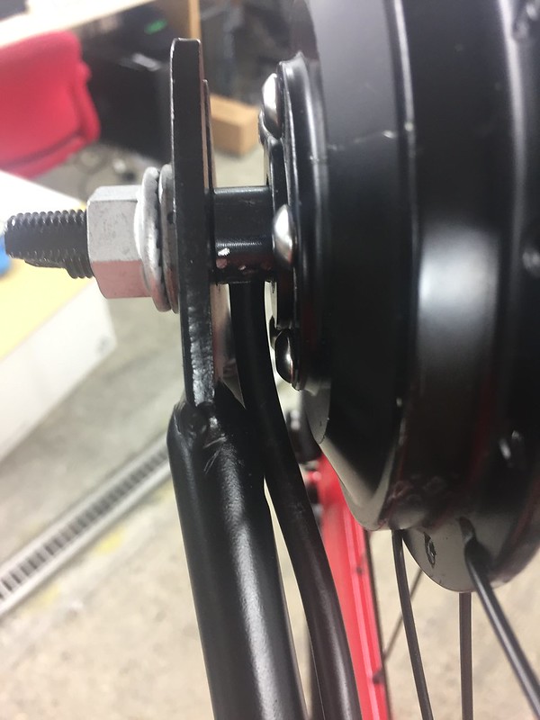
I never liked how the motor wire protrudes so much from the end of the axel. I've drilled a hole in the axel on the inside of the drop out, probably best I just post the photos.
30704481326_821454ed7e_c.jpg

Using the vice on the flat section of the axel to let me file the shaft and get a flat surface on the same plane as the top of the vice, making it parallel to the tangent.
30704402696_3fb71cd124_c.jpg

A bit of fiddling with a drill, file and die grinder later..
30440574410_e02ab91d8a_c.jpg

Wires in the motor at a good point to cut and splice together once shortered and I'm 100% sure the lengths are all right.
30440632440_917a942d77_c.jpg

30108977804_1198a0d3da_c.jpg

a bit of black on the filing marks and hopefully it will be completely hidden.
30652935641_b604f27415_c.jpg

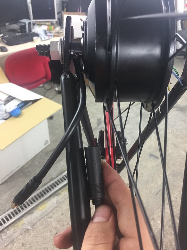
Rough positioning of the 'Juliet' connector. Fixing method to be determined, probably make a brake line style crescent profile slot to braze on.

Controller Packaging
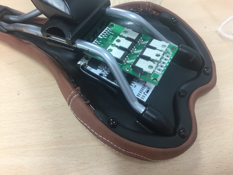
My new driver board for the motor has arrived. I'm hoping to fit it, the bms, and a little extra board I'll have to make up for throttle/torque sensor signal processing. I'm going to design a hard case to be 3d printed that can clip onto the metal bars of the saddle from the inside, this should let me swap it between saddles if I want because the dims of these are universal.
30624440692_5f83664573_c.jpg

30652868891_df922a7f00_c.jpg


Next Steps

-Finish off the batteries and fit connectors to all ends to make it easy to slot in/out.
-work out what i'm going to do about my knackered motor, find the root cause of the problem.
-Controller hardcase design
-Signal processing design

Saddle Bag

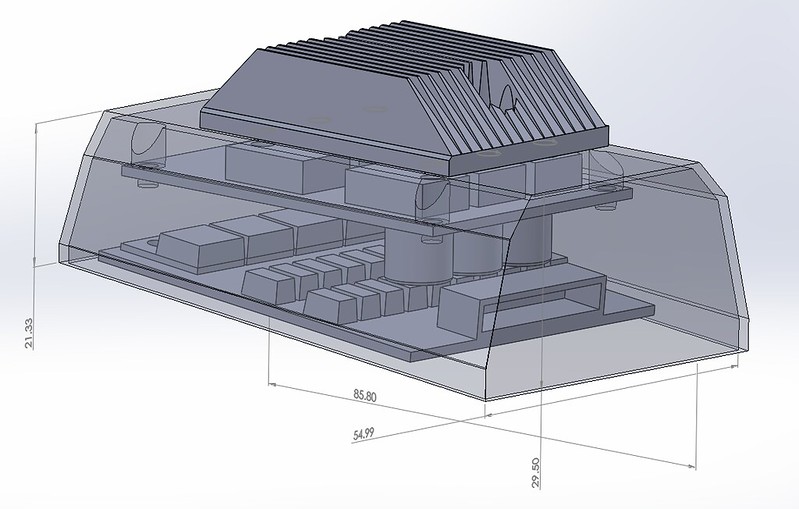
This is a quick mock up I've made of the hard case to go under the saddle. Dims in mm. (it's upside down, the heat sync would be the only bit visible from the side of the saddle).
30643198232_6f722b7540_c.jpg

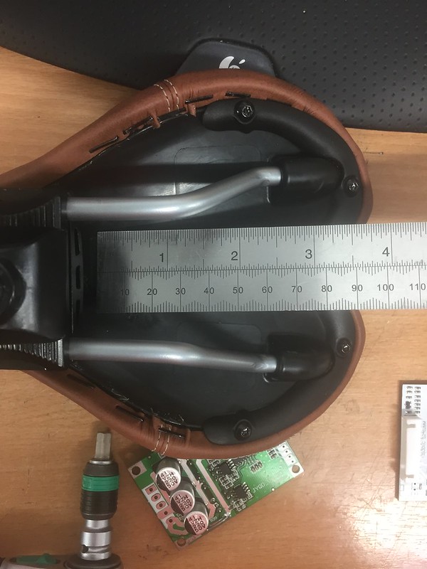
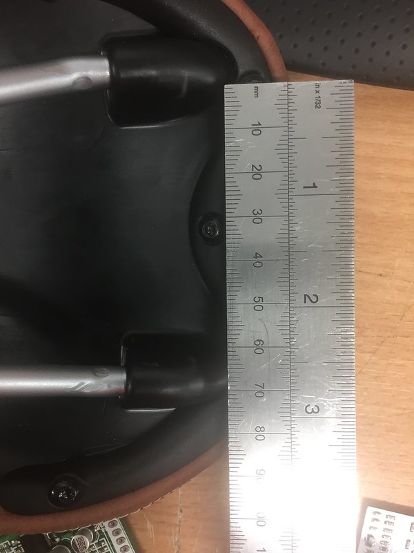
A few photos showing rough dimensions of the saddle.
30759886925_f04c0095bf_c.jpg

30643343402_f2f435a943_c.jpg

30759887175_6d16ddd9ca_c.jpg


Pretty tight packaging, but i'm sure with some good contact area to the heat sync it should stay cool, if not i'll know about it pretty quick through the saddle.
 
Back