You are using an out of date browser. It may not display this or other websites correctly.
You should upgrade or use an alternative browser.
You should upgrade or use an alternative browser.
Ultra Tuning: Decoding the Voltage Section of Torque Tab
- Thread starter smorgasbord
- Start date


smorgasbord
Well-Known Member
- Region
- USA
First and tenth posts in the thread have EggRider screenshots. Other screenshots are available in the "gone wrong" guides on the web, such as this one.Not following. Have some screenshots to explain for us thick headed folk?
JRA
Well-Known Member
I admit that there is some head scratching that needs to go into tuning an M620 for your needs. Before Smorgasboard took the time to understand the parameters and lay down the facts that he came up with and shared here it was really a catch as catch can deal sorting through a bunch of other "methods" that were quite frankly shots in the dark. I know as I went through them all and although I finally settled on a tune that by default really worked better than any of the screenshots I copied it was by modifying them blindly until I got what I could live with.Not following. Have some screenshots to explain for us thick headed folk?
If you take your time and read and understand each line item starting from the basic tab onwards you will get there. I would say that setting up your Continuous Get to establish your base voltage is the most critical step and also the easiest to do by following his directions. After some trials I got an entirely different result than my original tune that suits me way better as it is much more based on torque input over cadence and I feel I am getting more even power output and even better wh/mi usage than before.
So hang in there and even if you think you are thick headed if you apply yourself I think you can do it!
smorgasbord
Well-Known Member
- Region
- USA
Thanks, and yes I agree that the often misunderstood Voltage table needs to be setup right to make any of the subsequent tunings workable.If you take your time and read and understand each line item starting from the basic tab onwards you will get there. I would say that setting up your Continuous Get to establish your base voltage is the most critical step and also the easiest to do by following his directions.
In case @keithj69 was asking where to start, I have two answers:
Overall Ultra tuning, start with this thread:
Ultra Tuning: Master Thread -- Start Here!
If you're starting out to tune, or re-tune, your Bafang Ultra G620/M510 motor, you've come to the right place. There's a lot to setting up an Ultra to ride the way you want, but if you take it a step at a time it won't be as daunting. You don't have to do them all at once - I actually recommend...
 forums.electricbikereview.com
If asking about just the Voltage section, start with the 10th post in this thread, which is a step-by-step, here:
Ultra Tuning: Decoding the Voltage Section of Torque Tab
EDIT: This revised post corrects and updates previous information. Thanks to @ProphetZarquon for his insights! EDIT #2: See post #10 below for a How-To primer in case you don't want/need to understand but to try this out. Everyone should update their Base Voltage at least! I've undertaken yet...
forums.electricbikereview.com


Nvreloader
Western Nevada
- Region
- USA
Thanks Guys
Going back over all of it for the second time............some of it hasn't sunk in yet.
Going back over all of it for the second time............some of it hasn't sunk in yet.
smorgasbord
Well-Known Member
- Region
- USA
As a result of an off-board discussion, here is some additional information that might help you grok the Delta Voltage table. It's a different enough way to think about it that did some edits to the first and tenth post in this thread.
While the table is laid out such that the input is pedal force and the output is torque sensor voltage, it's better to think of that operation in reverse. That is, the Delta Table doesn't change the voltage that the torque sensor produces at any given pedal pressure, but rather changes how that voltage is re-interpreted back to pedal force. This is important, because the SPDxx table uses pedal force as its input to determine at any given wheel rpm what the motor current percentage should be.
To use the table backwards requires thinking about things somewhat differently. This worked with the person I was talking to:
1) The "Continuous Get" function on the programming software is always the output of the torque sensor, in milliVolts (mV).
2) Take the value produced at any given moment (call it "X"), and start by subtracting the Base Voltage from it to produce value "Y".
3) If "Y" is zero or less, report 0kg to the SpdXX table.
4) If "Y" is greater than or equal to the value in the 0-5kg entry, subtract the 0-5kg entry from "Y" to produce a new "Y."
5) Repeat for the 5-10kg, 10-15kg, etc. entries, until "Y" is no longer greater than the next table's entry.
6) If "Y" is zero, then the force sent to the SPDXX table is the high range value in the last entry subtracted.
7) Otherwise, divide Y by the next entry's to produce interpolated value "Z" (which will between 0 and 1). Use "Z" to interpolate between the two kg values in the next entry, the math for which is (low range value + high range value) * Z.
Some examples, using the values in the image in the first post of this thread (BaseVoltage=753, next 4 ranges all at 208, final 4 ranges at 416):
A) Live voltage read (X) is 1169mV:
• 1169 - 753(BaseVoltage) = 416 (Y)
• Y is greater than the 0-5kg range's value (208), so subtract to get a new Y: 416-208 = 208 (new Y)
• Y is equal to the 5-10kg range's value (also 208), so the force fed to the SPDxx table is 10kg
B) Live voltage read (X) is 1273mv:
• 1273-753 = 520 (Y)
• Y is greater than the 0-5kg range's value (208), so subtract to get a new Y: 520-208 = 312 (new Y)
• Y is greater than the 5-10kg range's value (208) so subtract to get a new Y: 312-208 = 104 (new Y)
• Y is not greater than 10-15kg's range's value (208), so divide Y by the 10-15kg's value, 208. That's 104/208 = 0.5 (Z)
• Resulting Force is (10+15)*0.5 = 12.5kg is fed to the SPDxx table.
Some ramifications:
• Bafang probably does something special if Base Voltage is left at 0mV, otherwise the SPDxx table would be producing some motor current even at a stand-sill. Setting Base Voltage too low probably overrides that special condition, so don't do that. It's pretty easy with the software or EggRider to see what the motor produces when you have no pressure on the pedals and then choose a value 1 or 2 mV above that. From a few reports, it seems that most values are 760 or less, so if for some reason you don't want to measure, put a value at or above 760 in.
• With the proper Base Voltage setting, as soon as you put any pressure on the pedals you'll get some motor output. How much depends on the entries in the SPD0 column, your PAS level, and until the pedal actually moves, the effects of 0 Speed Boost.
• Larger values in the lower ranges in the Delta Voltage table will reduce the pedal force fed to the SPDxx table. This is desirable both for getting a smooth start as well as for controllability since us humans can modulate lower pressures more effectively than higher pressures. It's pretty easy for us to modulate between 5 and 10 kg of force, for instance, but it's really hard for us to modulate between 55 and 60kg of force. This effect is also why the table entries start out at a 5kg spacing (0-5, 5-10, etc.) but end up at a 10 kg spacing (40-50, 50-60).
• If all the values you enter in the Delta Voltage table plus the Base Voltage sum up to greater than the maximum voltage the torque sensor produces (typically just under 3300mv), then you'll never have the 60kg force level sent to the SPDxx table. If you're a weaker/lighter rider, then you'll want a lower produced voltage number to reach that 60kg level so that you get full programmability in the SPDxx table. For instance, if you can only put about 50kg of force on the pedal, then your max voltage reading may be 2700mV and you'd want to use the instructions in posts #1 and #10 so that 2700mV is communicated as 60kg (which you'll get if all the numbers add up to 2700).
Last edited:
mcfizzlestag
New Member
- Region
- Canada
Just for reference, at the moment this screen doesn't display correct data on the current app/firmware. Eggrider devs have not finished on it yet. Believe everyone should see 1217 mV and no change with pressure.2A) For EggRider, Go to the Torque Settings tab, then click the "speedometer” looking link at the top right. This will bring up the "Torque Live Data" tab, which looks like this:
AndZab
New Member
Hello, I do not agree a lot with your point 10)How to Setup your Delta Voltage Table, step-by-step.
Follow Steps 1-7.
Then, if you're going to be happy with a linear Pedal Force to Motor Current mapping follow the first set of steps 8-13. Don't be discouraged by the number of steps, I've made each step easy and small. If you want to get fancy with progressive torque curves, then follow the second set of steps 8-14, which include downloading a spreadsheet I've created.
1) Hook up your EggRider as your display, or Bafang programming cable to the motor and Windows computer running the Bafang App.
2A) For EggRider, Go to the Torque Settings tab, then click the "speedometer” looking link at the top right. This will bring up the "Torque Live Data" tab, which looks like this:
View attachment 149866
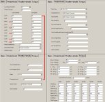
2B) For Bafang Windows App, go to the Torque Settings tab and click the "Continuous Get" button near the bottom.
3) Read the "Torque Voltage" (EggRider) or the "TqVoltate(mv) field and write that number down. Add 1 or 2 to that for use as your "Base Voltage".
4) Sit on the stationary bike and backwards rotate a pedal until it's horizontal in front.
5) With the brakes firmly applied (and perhaps a low PAS level), start to put pressure on that front pedal. The Torque Voltage/TqVoltate field should start to increase. If things feel safe, apply more and more pressure to that pedal until you're standing with all your weight on the pedal. If you don't weigh more than 133 pounds, that's OK. After riding more and thinking about it more, there's not much point in having the torque system go beyond what you're capable of when riding. If you have an EggRider, you can record your phone's screen while you're riding in this mode and then look over the video to see what the maximum voltage value you produce is.
6) Read/remember the maximum value you see. This is your Max Voltage (you don't enter this number into any setting, but you'll need it for future calculations).
7) Get off the bike carefully. If you're using the EggRider, click the "Settings Page" button to go back to the Torque Tab.
Now if you want to do a linear Torque to Motor Current map (I recommend doing the progressive, listed further below), do the following:
8) Do a "Read" to be sure you're looking at the settings currently in the motor.
9) Enter the new Base Voltage at the top.
10) Subtract Base Voltage from Max Voltage. Divide by 12, round fully up (209.1 -> 210) and enter that number into the top 4 Delta Voltage fields.
11) Enter double that number into the bottom 4 Delta Voltage fields.
12) Save/Write to the motor.
That's it!
But, if you want to get fancy and have a progressive/non-linear torque map, then you'll want to download this spreadsheet from my Google Drive:
View attachment 149873
8) Enter the Base Voltage into cell B1 and Max Voltage into B10 (green are cells you input, blue are your output values).
9) The cells B2 to B9 should then update. If you wanted a linear mapping you could enter those values into your Settings page now, but you didn't need this spreadsheet for that.
10) Decide how aggressive you want the progression to be. This spreadsheet is setup to create a symmetrical "S-curve" where the amount you modify the 4 lowest torque mapping is balanced by an equal modification in the other direction of the high torque mapping. The value in G10 shows the sum of your values, which should always equal Max Voltage-Base Voltage. If G10 is smaller then you'll never get MaxCur(%) in use, and if it's greater then you'll hit MaxCur(%) before you top off the pedal torque sensitivity range.
11) If you weren't able to max out the Voltage in Step 5, above, then you'll need to modify the calculations accordingly. If you don't know how to do this, DM me and I'll help you out.
12) I decided to try 175% on the lowest torques (0kg-5kg), 150% on the next level, 125% on the third level, and a 1:1 (100%) mapping in the middle. Note that putting 175% in F2 caused F9 to drop to 62.25%. Having a longer/smoother take off from no pedaling needs to be compensated for somewhere - I did that by having a shorter/faster ramp at the highest torques. The idea is that humans can modulate how much low torque they're applying pretty easily, but will have a hard time differentiating between a Kg of force at the high 50kg-60kg levels, so might as well just ramp away because the rider is pressing hard and simply wants MORE POWER!
13) Personally, I felt that keeping a linear mapping in the middle of the torque range was best, but you should be able to modify F5 if you disagree. You could also try putting in lower than 100% in the F2-F5 fields, which would have amps ramp up faster in the beginning, but that's probably going to create a more jerky take-off.
13) After entering F2-F5, everything should update. Copy the values in blue, G2-G9 into the appropriate fields in your Delta Voltage table.
14) Hit "Write" and go for a ride. Start at a low PAS level and carefully accelerate on level ground. If all seems good, you can start to raise the PAS level and try other things.
That's it. Oh, except the bottom of the spreadsheet shows the reverse math. In the green "A" column entries you can enter a pedal force being applied and 3 columns over see what force that will map to if you had, as Bafang defaults to, a linear Delta Voltage table. Here's a sample:
View attachment 153226
For the settings above, pressing down with 20 Kg of force is equivalent to pressing with 27.5 Kg of force if the values were default linear. These Output Kg values are the ones sent to the Spd Table in the rest of the Torque Settings tab, and that may help you decide what you want the Start/Full Kg and Min/Max Current % to be for those entries.
You can enter any value in the green fields to see what the result would be.
If you use this, please let me know - either here or via DM - how it worked out for you. If you find bugs in the calculations, or have suggestions for improvement, also let me know.
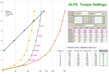
If you set Max Voltage at 1550 mV like my settings on attach (green curve), you can reach full motor power with little force on pedals...
Attachments
smorgasbord
Well-Known Member
- Region
- USA
Hi AndZab, thanks for looking into this. I personally find the Delta Voltage Table to be the most confusing part of Ultra tuning, as the table works backwards and each row is additive to the previous rows. So, it's certainly possible that I mis-stated something along the way. Let's look into this a bit deeper:Hello, I do not agree a lot with your point 10)
If you set Max Voltage at 1550 mV like my settings on attach (green curve), you can reach full motor power with little force on pedals...
First, note that the final motor assist achieved is a combination of not just the Delta Voltage Table, but also the SPD Table as well as the PAS levels in the Basic Tab. The force you apply to the pedals is converted by the torque sensor to a voltage (in milli-Volts). That voltage is then mapped to a force (in Kg) via the Delta Voltage Table. And then, here's an edited portion of a piece from first post in the SPD Table thread:
When you press on the pedals, the Ultra's torque sensor outputs a voltage based on the force being applied. The Delta Voltage table specifies how that voltage is converted to a Kg, and that Kg number is used by the Spd Table's Start, Full, and Return parameters to return what I call a Percentage of Current (POC) as determined by the MinCur, MaxCur, and KeepCur parameters to be sent down the controller pipeline:
What gets confusing (at least to me) is that we have a force coming in and a force value coming out, and a Delta Voltage Table that's not linear and not covering the full range will mean those two "forces" aren't the same. Add in that this is just the first step in a multi-step pipeline that determines the actual motor assist.
- The rider-applied pedal force is converted into the POC using a linear mapping: Start(Kg) produces MinCur(%) while Full(Kg) produces MaxCur(%). Values between Start and Full result in values equally interpolated between MinCur and MaxCur.
- That POC is multiplied by the current PAS level's "Limit Current(%)" (specified on the Basic tab), which is then multiplied by the "LimitedCurrent(A)" [really Current Limit, in Amps], which is also specified on the Basic tab, to arrive at an actual Current value, in amps
- That Current essentially controls the power output of the Ultra motor (Volts * Amps = Watts, a unit of power)
You are correct that with the values in your "DELTA Alps" column, you'll output from the Delta Voltage Table the maximum value of 60Kg at lower actual pedal pressures. The values in the column sum up to 1550, which is lower than the torque sensor's maximum output of about 3260. From my spreadsheet, it looks like somewhere around an actual pressure of 20Kg on the pedals will create a "60Kg" output from the Delta Voltage Table.
So, if you're referring to bullet point #10 (progressive edition) in post #10, then you are correct that this sentence is wrong:
In fact, it's the exact opposite. I'll edit the post accordingly - thanks for the catch! I do believe, however, that the rest of the post(s) are correct, but please call out anything else you find.If G10 is smaller then you'll never get MaxCur(%) in use, and if it's greater then you'll hit MaxCur(%) before you top off the pedal torque sensitivity range.
-----
If I'm correct that your Delta Voltage Table outputs 60Kg to the SPD Table at only 20Kg of actual physical pedal pressure, then your SPD "Full(Kg)" table values provide an additional curve to the power boost at low pedal pressures. At SPD0, for instance, your Full(Kg) value is only 45, so with 20Kg of actual force producing 60 into that, you reach the MaxCur(%) of 100% at only 15Kg of actual pedal force (45/60 * 20). And, at SPD100, with a Full(Kg) value of 10, you'll reach 100% at only (10/60 * 20) at only 3.33 Kg of actual pedal force.
The way I've gone about describing how to tune the Ultra is not about getting maximum power at low pedal pressures - it's to provide a natural feeling pedal-pressure to assist-force curve. I feel the Delta Voltage Table should be set such that you get the largest range of values possible given your ability to provide pedal pressure. If you can apply a full 60Kg of force in some of your riding, then I feel you should take advantage of the full range of output from that table. Having the table send out a "60 Kg" number to the SPD table when you're applying only 20 Kg of force means that you'll never get any benefit from applying more then 20 Kg of force on the pedals. That may be what you want (or need if you have physical issues), but for myself I'd rather have a larger range of pedal pressures to work with, and then adjust based on bicycle speed in the SPD table.
AndZab
New Member
Dear smorgasbord, thank you so much for your in-depth explanations.Hi AndZab, thanks for looking into this. I personally find the Delta Voltage Table to be the most confusing part of Ultra tuning, as the table works backwards and each row is additive to the previous rows. So, it's certainly possible that I mis-stated something along the way. Let's look into this a bit deeper:
First, note that the final motor assist achieved is a combination of not just the Delta Voltage Table, but also the SPD Table as well as the PAS levels in the Basic Tab. The force you apply to the pedals is converted by the torque sensor to a voltage (in milli-Volts). That voltage is then mapped to a force (in Kg) via the Delta Voltage Table. And then, here's an edited portion of a piece from first post in the SPD Table thread:
What gets confusing (at least to me) is that we have a force coming in and a force value coming out, and a Delta Voltage Table that's not linear and not covering the full range will mean those two "forces" aren't the same. Add in that this is just the first step in a multi-step pipeline that determines the actual motor assist.
You are correct that with the values in your "DELTA Alps" column, you'll output from the Delta Voltage Table the maximum value of 60Kg at lower actual pedal pressures. The values in the column sum up to 1550, which is lower than the torque sensor's maximum output of about 3260. From my spreadsheet, it looks like somewhere around an actual pressure of 20Kg on the pedals will create a "60Kg" output from the Delta Voltage Table.
So, if you're referring to bullet point #10 (progressive edition) in post #10, then you are correct that this sentence is wrong:
In fact, it's the exact opposite. I'll edit the post accordingly - thanks for the catch! I do believe, however, that the rest of the post(s) are correct, but please call out anything else you find.
-----
If I'm correct that your Delta Voltage Table outputs 60Kg to the SPD Table at only 20Kg of actual physical pedal pressure, then your SPD "Full(Kg)" table values provide an additional curve to the power boost at low pedal pressures. At SPD0, for instance, your Full(Kg) value is only 45, so with 20Kg of actual force producing 60 into that, you reach the MaxCur(%) of 100% at only 15Kg of actual pedal force (45/60 * 20). And, at SPD100, with a Full(Kg) value of 10, you'll reach 100% at only (10/60 * 20) at only 3.33 Kg of actual pedal force.
The way I've gone about describing how to tune the Ultra is not about getting maximum power at low pedal pressures - it's to provide a natural feeling pedal-pressure to assist-force curve. I feel the Delta Voltage Table should be set such that you get the largest range of values possible given your ability to provide pedal pressure. If you can apply a full 60Kg of force in some of your riding, then I feel you should take advantage of the full range of output from that table. Having the table send out a "60 Kg" number to the SPD table when you're applying only 20 Kg of force means that you'll never get any benefit from applying more then 20 Kg of force on the pedals. That may be what you want (or need if you have physical issues), but for myself I'd rather have a larger range of pedal pressures to work with, and then adjust based on bicycle speed in the SPD table.
I totally agree with your reverse engineering studies.
Also I went to similar conclusions a few years ago, when I done my bike setup.
Apart my weird configuration for "light feet" people, I didn't understand wery well the road-speeds subdivisions of the Spd table.
It's not clear to me what is the more convenient FullKg "profile" for super steep mountain. Frequently I need the maximum power between 6 and 12 kmh, while at 20 kmh I do not need power because it's easy I'm on a flat track.
Do you have the exact road-speeds ranges of Spd table, for normal magnet setup ? (1 magnet)
Maybe I need a fine tuning of Spd20 and Spd40, but first I'd like to know the precise road-speeds involved with them (my max speed is 25 kmh)
Thank you very much for your help.
Best Regards from the Venice area, Italy
Attachments
smorgasbord
Well-Known Member
- Region
- USA
The first post in this thread has this table:Frequently I need the maximum power between 6 and 12 kmh, while at 20 kmh I do not need power because it's easy I'm on a flat track.
Do you have the exact road-speeds ranges of Spd table, for normal magnet setup ? (1 magnet)
| SpdXX | In KPH | Out KPH |
|---|---|---|
| Spd0 | 0.01 | 4.5 |
| Spd20 | 2 | 8.5 |
| Spd40 | 6 | 13.5 |
| Spd60 | 10 | 18 |
| Spd80 | 16 | 25 |
| Spd100 | 20 | > 40 (never stopped) |
But, remember that the speed changes are smoothed and overlapped. For instance, at 7 KPH, you getting some of SPD20's values and some of SPD40's values. Only where there is no overlap do you get just one column's speed: for instance on a road speed from 8.51 KPH to 9.99 KPH are you getting just SPD40's values.
And again, this assumes your bike is set to the actual proper wheel size/circumference for both display and the Basic Tab. There's a lot more information on the SPD table in that thread, as I linked above.
Last edited:
AndZab
New Member
Dear smorgasbord, thanks a lot for this table, very useful.The first post in this thread has this table:
SpdXX In KPH Out KPH Spd0 0.01 4.5 Spd20 2 8.5 Spd40 6 13.5 Spd60 10 18 Spd80 16 25 Spd100 20 > 40 (never stopped)
But, remember that the speed changes are smoothed and overlapped. For instance, at 7 KPH, you getting some of SPD20's values and some of SPD40's values. Only where there is no overlap do you get just one column's speed: for instance on a road speed from 8.51 KPH to 9.99 KPH are you getting just SPD40's values.
And again, this assumes your bike is set to the actual proper wheel size/circumference for both display and the Basic Tab. There's a lot more information on the SPD table in that thread, as I linked above.
From your writings I understood that second magnet is very important, for normal speed configuration, too.
But on my wheel the two magnets can't stay exactly at 180°. They can stay at about 185 or 175, because spokes configuration.
Do you believe this is a big problem ?
Thank you very much for your help
smorgasbord
Well-Known Member
- Region
- USA
I do NOT recommend using two actual magnets.From your writings I understood that second magnet is very important, for normal speed configuration, too.
But on my wheel the two magnets can't stay exactly at 180°. They can stay at about 185 or 175, because spokes configuration.
If you have an EggRider or some other display that can set a large wheel diameter, then you can fake out the Ultra to thinking it had two magnets, but actually has only one. That doubles the speeds the SPD table uses, which can be advantageous for on road riding, where you go faster.
ProphetZarquon
Active Member
- Region
- USA
I find it extremely annoying that I can't adjust the torque-sensing & per-Spd levels for each PAS mode, because the cuts made by each PAS mode stack in addition to the adjustments available on the Torque tab; so, any settings calibrated for ideal graduation in PAS 1 are far from ideal in PAS 5, & vice versa!It's not clear to me what is the more convenient FullKg "profile" for super steep mountain. Frequently I need the maximum power between 6 and 12 kmh, while at 20 kmh I do not need power because it's easy I'm on a flat track.
Plus, on the PAS modes presented by the DPC- display we've got, I switch between Eco & Sport pretty regularly, which yet again produces dramatically different run-on times etc, & I have also set PAS 0 to apply mild assist, the way PAS 1 is normally used (for zero assist I can instead just turn the system off!?), so technically I've got 6+6 PAS modes... of which only one can ever be well calibrated.
smorgasbord
Well-Known Member
- Region
- USA
I'd like to hear more about that. With the EggRider at least, I find no differences between Sport and Eco (aka Off-Road and Road) when everything we can set is set to the same.I switch between Eco & Sport pretty regularly, which yet again produces dramatically different run-on times etc,
AndZab
New Member
If you have DPC-18 display, set everytime SPORT, to enable the custom programming. From what I undestood, ECO is a factory preset.I find it extremely annoying that I can't adjust the torque-sensing & per-Spd levels for each PAS mode, because the cuts made by each PAS mode stack in addition to the adjustments available on the Torque tab; so, any settings calibrated for ideal graduation in PAS 1 are far from ideal in PAS 5, & vice versa!
Plus, on the PAS modes presented by the DPC- display we've got, I switch between Eco & Sport pretty regularly, which yet again produces dramatically different run-on times etc, & I have also set PAS 0 to apply mild assist, the way PAS 1 is normally used (for zero assist I can instead just turn the system off!?), so technically I've got 6+6 PAS modes... of which only one can ever be well calibrated.
In my custom setup you can see the levels L1 - L5 for the DPC-18 display
Attachments

smorgasbord
Well-Known Member
- Region
- USA
The motor controller doesn't know what display is connected to it, it only knows what parameters have been set via the display cable input. For ECO to be some kind of "factory preset" would mean that on power-up it always resets at least parameters in the Ultra motor controller. I strongly doubt this is occurring. It could be checked by using the computer program via the commonly available programming cable to set parameters, save them, then disconnect the programming cable, reconnect the DPC-18 (or any other display) and go for a ride. Then, re-connect the computer and see what parameters, if any, were changed by the display. Again, I doubt there would be any changes.From what I undestood, ECO is a factory preset.
The levels you marked for the 5-level Sport setting are interesting to me. Did you also check to see if the 5-level ECO setting used Assist1, Assist3, Assist5, Assist7, and Assist9?In my custom setup you can see the levels L1 - L5 for the DPC-18 display

lilyelliott4
New Member
- Region
- Other
I totally get where you’re coming from — it can be really frustrating when the torque-sensing and PAS levels can’t be tuned independently. Since the adjustments on the Torque tab stack with the PAS settings, it’s almost impossible to get smooth, consistent behavior across all levels.I find it extremely annoying that I can't adjust the torque-sensing & per-Spd levels for each PAS mode, because the cuts made by each PAS mode stack in addition to the adjustments available on the Torque tab; so, any settings calibrated for ideal graduation in PAS 1 are far from ideal in PAS 5, & vice versa!
Plus, on the PAS modes presented by the DPC- display we've got, I switch between Eco & Sport pretty regularly, which yet again produces dramatically different run-on times etc, & I have also set PAS 0 to apply mild assist, the way PAS 1 is normally used (for zero assist I can instead just turn the system off!?), so technically I've got 6+6 PAS modes... of which only one can ever be well calibrated.
Switching between Eco and Sport makes it even trickier, especially with the different run-on times and responsiveness. Using PAS 0 for mild assist is a clever workaround, but I understand how having effectively 6+6 PAS modes without proper individual calibration becomes a headache.
Hopefully, we’ll see a firmware update or display option in the future that allows separate tuning for each PAS mode — that would make dialing in a balanced setup so much easier.
smorgasbord
Well-Known Member
- Region
- USA
Sorry for being pedantic, but they don't really "stack," as in being additive. They're multiplicative, with the PAS providing an upper limit of power and the Torque/Voltage providing a percentage of that.Since the adjustments on the Torque tab stack with the PAS settings,
I've seen no differences in either between Eco and Sport. All those seem to do is choose which of the 10 levels is available to be selected. If you have all 10 enabled, then there's zero difference.Switching between Eco and Sport makes it even trickier, especially with the different run-on times and responsiveness.
Bafang has moved on from this model of motor, has changed how their newer motors are programmed. It's unlikely we'll see any changes for the Ultra motors.Hopefully, we’ll see a firmware update
Similar threads
- Replies
- 9
- Views
- 4K
- Replies
- 24
- Views
- 15K
- Replies
- 0
- Views
- 936
- Replies
- 0
- Views
- 3K