Sensored Motor Controller Wiring Manual Deciphering

stonestonestone

New Member
Region
USA
I'm about to buy this Motor controller from pswpower
6f4e37436f.png

But for the life of me, I cannot understand what this is supposed to mean:
"Note:This is sensor controller, so controller has three big cable and five sensor wires and one speed sensor wire. you motor must have 8pcs wires or 9pcs wires, If you motor just three big cable, please buy sensorless controller."
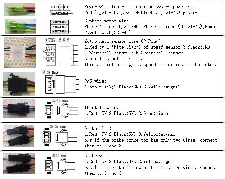
My motor has 3 phase wires. Also, there is a five pinned connector and a single pin connector. Is that the 9pcs? That means my motor has a sensor?
What's weird is that on the data sheet it shows the hall sensor as a 6pin, even though it said theres only 5 sensor wires? Also, the speed sensor wire as a 3pin- even though it should be a 1 pin?
HTB1MoktMXXXXXXmXVXXq6xXFXXXx.jpg

HTB1zrcwMXXXXXXsXVXXq6xXFXXXH.jpg
 
My motor has 3 phase wires. Also, there is a five pinned connector and a single pin connector. Is that the 9pcs? That means my motor has a sensor?

If your motor has those 9 wires going to it, then you have motor sensors.

The 3 Fat blue, green, and yellow wires are your phase wires.
They deliver the power to the motor.

The 3 skinny blue, green, and yellow wires are your sensor wires that monitor your phase wires to let the controller know where your motor is at.
The sensor and phase wires are ALWAYS paired together. Blue to blue, green to green, and yellow to yellow.

Then you've got your +5V powering your sensors. Red is positive, and black is negative.

And finally you've got your speed sensor wire which sends a pulse to your controller to indicate your speed.

The only other wire that could come out of your hub motor is a temperature sensor wire but a temperature sensor is extremely rare, and is normally only found on Huge motors.
 
Last edited:
What's weird is that on the data sheet it shows the hall sensor as a 6pin, even though it said theres only 5 sensor wires?

That 6th pin is for the temperature sensor and most motors don't have a temperature sensor.

Also, the speed sensor wire as a 3pin- even though it should be a 1 pin?

The speed sensor output wire is white. The red and black are positive and negative.

The speed sensor can be powered by the red and black hall sensor power wires, so then you would only have the single white wire as a speed sensor output.

This is the thread where I posted about my KT install.
It's kind of a scattered mess, but it might have some useful information and pictures,..

 
I bought the KT controller with the waterproof plugs and it doesn't have all these connectors with jumper wires to turn things on and off,..

Screenshot_20240530-101416_AliExpress.jpg


I turn my cruise control on and off with the display, as well as adjust the power and speed settings with the display.

I don't know how this controller would behave if you were to activate the cruise control with the jumper wire, then shut it off with the display, or vice versa?

Same with the speed/power limiter?
They may work in combination with each other to further reduce the power?

The lamp and speaker connector is probably for lights and horn, but I'm not sure?
(Or it's for hooking up a stereo with disco lights? 😂)

My waterproof controller has a separate plug on the 1-5 cable for the headlights, and is turned on and off with my display.
(If I didn't have a headlight, then I would use the 1-4 cable instead, without the light output plug.)

The EABS jumper wire is for turning the regeneration braking on and off, but as far as I know most geared hub motors have a clutch and will not have regenerating braking.
 
There's a lot of wires on that KT controller. I don't need EABS, cruise, or the lights. I cut those off, pull the wires inside the case and tape them up. Many motors have speed sensors built in, and the 6 pin rectangular plug will pick it up if present.

Be glad you have a white wire for the motor's internal speed sensor. It uses 5V power and ground from the Hall sensors in the motor, so you run the white wire from the motor to the 2x3 connector.

If your motor did not have a speed sensor, some don't, then you would fit an external sensor and run it to the extra three ping connctor provided. I've had that speed sensor burn out in two motors. and I've had to add the external sensor as a work around.
 
Back