L4rkb0x
New Member
- Region
- United Kingdom
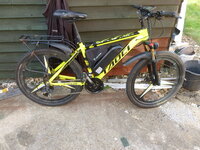
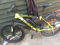
I have been given an 'old' (according to the hub motor 16 months old) taoci 02 amazon special ebike.
I have been slowly working on this bike and this weekend last the delivery from china arrived with a new kt 17a(peak) 8a controller lcd3 headset, julet leads, brake levers with integral sensors, a new bigger box for the controller and everything else i thought i needed.. so i have been busy.
Things have gone well for the most part but before chopping off the pas sensor julet socket from the controller and hacking in the existing right side pas sensor partly due to not knowing the what wire is what, i thought it would be a good idea to test out pas cycling using one of the 2 left hand side crank pas sensors i have 1 brand new, and 1 I replaced with a right side sensor due to an over sized crank issue (>17mm diameter) on my daily ride. Neither worked??
So?
Either the pas sensors i have with julet connectors are wired differently from the julet connector from the KT controller?
OR the new sensor I bought is faulty AND the one i was using on my daily ride and was working while slipping off the larger crank diameter regularly stopped working while stored?
OR pas is not turned on by default in the KT controller ??
Im dismissing the Pas not turned on for the time being as the speed control trigger worked straight away and the controller responds to change pas level inputs although ive not blown up the pdf manual to read yet (cataracts, im typing with a 46" screen atm.. ) but a squint over the dbl sided a4 sheet supplied with the headset didnt reveal anything relevant.
SO
Q1) Can i kill a pas hall effect sensor wiring/plugging it in incorrectly?
Q2) If Not...... Can i validate a sensor using a 5v power supply monitoring the signal wire with a multimeter/voltage<20v to the sensor probe(red) and ground or -ve 5v on the common probe(black), and passing a strong magnet over the sensor?? or perhaps 100ohm resistor in series with a led for an indicator??
Q3) IF So.. Is determining the wiring of the right hand pas sensor with a jst connector doable with the Q2 test and trial and error???
Q4) can I test the controller wiring by trial and error when i know the wiring of my sensors that have been proven valid without killing the controller.
Thanks in advance..
Progress so far...


The 17a controller was too big for the original controller box, the larger box i bought would not fit within the space available so i found a use for the redundant controller bag that was supplied gratis with my daily ride conversion kit.
the free wire hanging out of the controller bag zip is the brand new left hand side crank pas sensor plugged into the controller for testing, the jst terminated sensor is fed in with the rest of the wrapped wiring. I need more wrap for the front cabling (on order)
Yes the handlebars are the wrong way round, the were rotated to a dropped position, rotating back up revealed the need to flip the bars too
21 speed... No Currently only 18 speed both front and rear gear derailleurs were buried in wet mud for months and were rusted solid on arrival, bagging with penetrating oil for a week or so in the sun and a bit of manual manipulation got things moving again.. but the front derailleur (thank whatever god u imagine for spellcheck) will only shift between 2 chain rings and the tuning screws are still seized solid atm. I need more penetrating oil.. so ive positioned it over the larger of the two chain rings for now.
Ive managed to kill the rear gear position display when changing the cable i must have misplaced the top aspect and the tiny plastic pin that gets dragged has snapped off, my attempt to superglue it back in place resulted in my pin prick transferred blob of glue swamping the area and sticking everything in place DOH!
Brakes.. the only aspect of the bike that has been no problem, the rear calliper needed a lot of adjustment and packing washers but works a treat and the front brake WOW!! 1st time with disk brakes on a cycle WOW!
While pedal assist is inactive, speed control surely isnt Ive only ridden it up and down a side rd with no traffic but it hits 22mph and possibly with a longer run may go faster
I have been slowly working on this bike and this weekend last the delivery from china arrived with a new kt 17a(peak) 8a controller lcd3 headset, julet leads, brake levers with integral sensors, a new bigger box for the controller and everything else i thought i needed.. so i have been busy.
Things have gone well for the most part but before chopping off the pas sensor julet socket from the controller and hacking in the existing right side pas sensor partly due to not knowing the what wire is what, i thought it would be a good idea to test out pas cycling using one of the 2 left hand side crank pas sensors i have 1 brand new, and 1 I replaced with a right side sensor due to an over sized crank issue (>17mm diameter) on my daily ride. Neither worked??
So?
Either the pas sensors i have with julet connectors are wired differently from the julet connector from the KT controller?
OR the new sensor I bought is faulty AND the one i was using on my daily ride and was working while slipping off the larger crank diameter regularly stopped working while stored?
OR pas is not turned on by default in the KT controller ??
Im dismissing the Pas not turned on for the time being as the speed control trigger worked straight away and the controller responds to change pas level inputs although ive not blown up the pdf manual to read yet (cataracts, im typing with a 46" screen atm.. ) but a squint over the dbl sided a4 sheet supplied with the headset didnt reveal anything relevant.
SO
Q1) Can i kill a pas hall effect sensor wiring/plugging it in incorrectly?
Q2) If Not...... Can i validate a sensor using a 5v power supply monitoring the signal wire with a multimeter/voltage<20v to the sensor probe(red) and ground or -ve 5v on the common probe(black), and passing a strong magnet over the sensor?? or perhaps 100ohm resistor in series with a led for an indicator??
Q3) IF So.. Is determining the wiring of the right hand pas sensor with a jst connector doable with the Q2 test and trial and error???
Q4) can I test the controller wiring by trial and error when i know the wiring of my sensors that have been proven valid without killing the controller.
Thanks in advance..
Progress so far...


The 17a controller was too big for the original controller box, the larger box i bought would not fit within the space available so i found a use for the redundant controller bag that was supplied gratis with my daily ride conversion kit.
the free wire hanging out of the controller bag zip is the brand new left hand side crank pas sensor plugged into the controller for testing, the jst terminated sensor is fed in with the rest of the wrapped wiring. I need more wrap for the front cabling (on order)
Yes the handlebars are the wrong way round, the were rotated to a dropped position, rotating back up revealed the need to flip the bars too
21 speed... No Currently only 18 speed both front and rear gear derailleurs were buried in wet mud for months and were rusted solid on arrival, bagging with penetrating oil for a week or so in the sun and a bit of manual manipulation got things moving again.. but the front derailleur (thank whatever god u imagine for spellcheck) will only shift between 2 chain rings and the tuning screws are still seized solid atm. I need more penetrating oil.. so ive positioned it over the larger of the two chain rings for now.
Ive managed to kill the rear gear position display when changing the cable i must have misplaced the top aspect and the tiny plastic pin that gets dragged has snapped off, my attempt to superglue it back in place resulted in my pin prick transferred blob of glue swamping the area and sticking everything in place DOH!
Brakes.. the only aspect of the bike that has been no problem, the rear calliper needed a lot of adjustment and packing washers but works a treat and the front brake WOW!! 1st time with disk brakes on a cycle WOW!
While pedal assist is inactive, speed control surely isnt