stonestonestone
New Member
- Region
- USA
I'm about to buy this Motor controller from pswpower
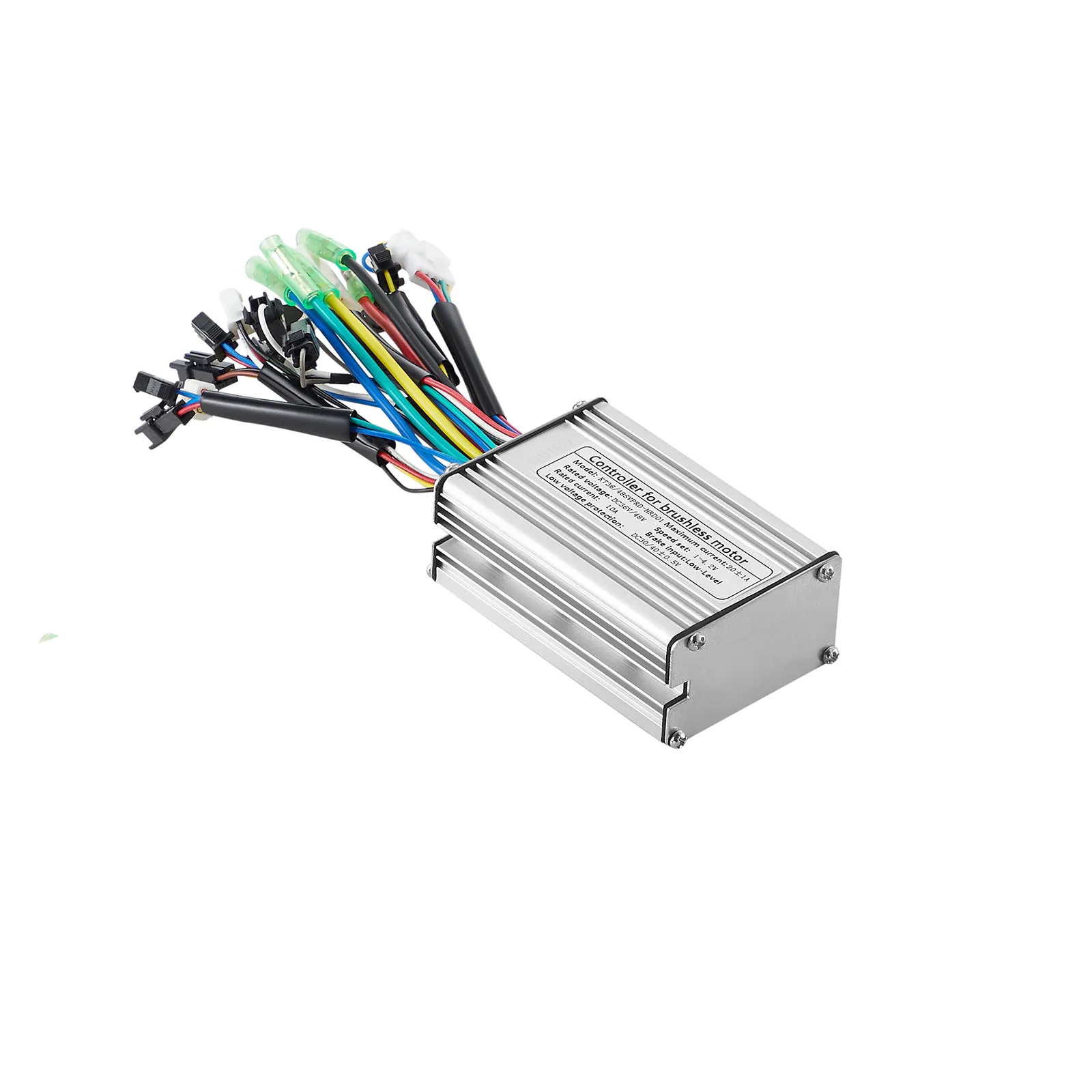
But for the life of me, I cannot understand what this is supposed to mean:
"Note:This is sensor controller, so controller has three big cable and five sensor wires and one speed sensor wire. you motor must have 8pcs wires or 9pcs wires, If you motor just three big cable, please buy sensorless controller."
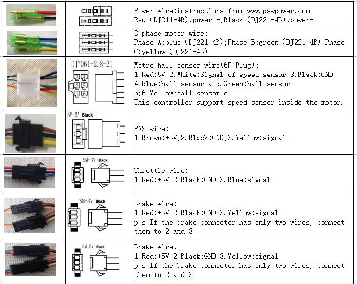
My motor has 3 phase wires. Also, there is a five pinned connector and a single pin connector. Is that the 9pcs? That means my motor has a sensor?
What's weird is that on the data sheet it shows the hall sensor as a 6pin, even though it said theres only 5 sensor wires? Also, the speed sensor wire as a 3pin- even though it should be a 1 pin?

But for the life of me, I cannot understand what this is supposed to mean:
"Note:This is sensor controller, so controller has three big cable and five sensor wires and one speed sensor wire. you motor must have 8pcs wires or 9pcs wires, If you motor just three big cable, please buy sensorless controller."
My motor has 3 phase wires. Also, there is a five pinned connector and a single pin connector. Is that the 9pcs? That means my motor has a sensor?
What's weird is that on the data sheet it shows the hall sensor as a 6pin, even though it said theres only 5 sensor wires? Also, the speed sensor wire as a 3pin- even though it should be a 1 pin?


 )
)

 )
)
 per revolution,..