BretCahill
New Member
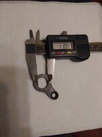
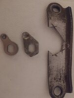
These bikes were assembled in Belgium with an 11 mm torque arm. (See photo of broken torque arm.) At higher assists the slack between axle and torque arm allows a build up of enough angular momentum to ream the torque arm when it engages. The axle then reels up the wires ripping them out of the circuit board. Incredibly the circuit board can withstand multiple 600 Newton "events." The hardest part of the repair is desoldering the high temperature solder. For some reason I find restringing and truing the wheel soothing.
I imagine a lot of these otherwise great bikes got dumped simply because no one checked the torque arm. We paid $1,000 for two GO Swissdrives on Gub frames, Hygia brakes, Ferei lights, etc.
I may eventually want a higher assist. A 10mm open wrench fits the axle perfectly and I may resort to that rig but is there any way to source a 10mm torque arm? A GO Swissdrive owner in Geneva managed to cajole an email address from the receptionist at Ortlinghaus but that contact info was never posted online. Eventually they sold him a rebuilt motor so GO Swissdrive may still be more or less supported in some limited capacity.