Chargeride
Well-Known Member
I havent looked at this, how is phase current higher than battery current, is it lower voltage or different way of measuring it.
I have posted that I swapped out a 75Ow motor, it had different size bearing internal diameter and shaft profile differences.
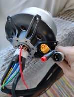
I totally agree with you.
The G062 is just for a baseline design.
I want to build my own motor design.
But I want it to fit inside the stock G062 motor case so anyone who has a compatible case can just drop in the upgrade.
So right now I am developing the baseline parameters. And looking for advice from all of you based on your experiences.
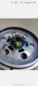
Everything inside the motor is fairly easy for me to make. Other than the stator.
The stator really isn't a big issue. If it could be solid it would be super simple.
But I know it can't because of eddy currents.
Based off the Grin All-Axel Hub Motor (I assume they have a really good design they seem to know there stuff)
QUOTE
So those are a few things to think about.
- 0.35mm Laminations for low motor drag when pedaling unassisted
- Thermistor Beta: The 10K NTC thermistor has been changed from one with a 3950 Beta constant to a 3450 Beta constant. This allows for better resolution and accuracy when measuring high motor temperatures, as there is a more discernable voltage change.
- updated from N35 to N40 grade magnets. Stronger magnets allow the motor to produce more torque for hill climbing with less heat loss, but they also increase the drag of the motor when riding without power
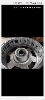
My main concern is the laminations. Those are .01378 inches thick. that is too thin to machine alone.
But if I clamp the plates together with a fixture I could easily machine them.
So how to you laminate the laminations?
Varnish Dip?
High Temp Epoxy Spray Paint?
Or just the glue in between laminations ? (what kind of glue?)
And what is the absolute best material to use for the laminations?
Again just to reiterate, I can and will make the tooling and fixtures required to assemble the stack.
I want to have the Best of the Best of the Best. And I find making my own stuff gets me there. And I love this hobby.
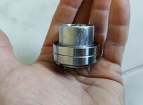
Another easier option may be to find a stock lamination stack at a lamination manufacturer that has enough material on it to machine it to my own specification?
Trust me. I can machine the stack without heat damage or pulling it apart. I got a half million dollar machine to do it with and the proper tooling and the proper knowledge.
I simply need to know What to Make.
I'm using ASI BAC2000 and Kilowatt app where you can adjust both independently. Basically at low rpm the voltage is also lower so phase amps can be higher than battery amps.I havent looked at this, how is phase current higher than battery current, is it lower voltage or different way of measuring it.
Liquid and and air cooling. Also 8 awg phases etc.
Couple of pictures to illustrate. Made custom part for added inlets. Also modded the cover plate and stator body a bit. Varmished coils run besides windings. Coolant is pumped and circulated through fan cooled radiator.How did you add in the Liguid cooling?
Where are the passages inside the motor to cool the stator?
Are they built into the Case?
That solution won't work as the cover is spinning but windings are not.I see that you ran copper tubing.
Once I get this motor 3D modeled I will take a look and see if there is a way to make the motor cover itself have the cooling ports inside.
If I can fit things right maybe I will have a cooling Ring that is built into the motor cover that will press down flat on top of the coils to get good surface area and thermal transfer between the cooling ring and coils.
I have to model everything so I can see what space I have inside the motor, I need to see also how much room I have between the bike frame and the outside of the motor case. If I can find at least say 6mm (1/4") that would be enough room. this space includes the Clearence in the motor the thickness of the case, and any extra room between the dropouts and the motor case.
Hopefully I can come up with a side cover that has the cooling ring built in. Then anyone wanting this upgrade could do so by changing the cover.
If I understod right this is pretty much how I did it. On the other side of the motor this won't work. There is both freewheel/free hub assembly and most importantly rotor/Bell housing on the way (picture) + the clutch assembly.I Plan to totally redesign the motor case.
I will machine it from aluminum bar stock.
By installing large bearings and modifying the shaft accordingly. The ring that is between the shaft and the bearing inner diameter will remain stationary.
Then holes can be machined into that ring for phase wires. Additional ports to make connection to the cooling ring will also be added. This can be done on both sides of the motor. If there is enough space. My motor comes Thursday so that will be the day I will truly know what I'm working with. For sure it's gonna be some work, but wow wouldn't that be truly awesome.
Did not make any mods in this regard to the rotor side. I did make room for wiring and tubing on the stator side only + the cover plate.All the added connections goes through cover plate through this custom part.I don't see any routing or connections anywhere. Did you machine the webbed face of the bore to make clearence.
I see the turn lines ( machining marks on that surface ).