That looks like some fun riding! Curious what brand 45a controller you are using that is running "well" sensorless?This is the 45 amp controller, the dunes are just the right size that I don't risk overheating anything and can use full power even though the sand is quite a drag on the bike, running sensorless on a cheap Chinese controller, it works fine, only loses track once every few rides and I am always pushing it to the limit.
You are using an out of date browser. It may not display this or other websites correctly.
You should upgrade or use an alternative browser.
You should upgrade or use an alternative browser.
Bafang G062 / G063 Info
- Thread starter Boosted
- Start date


Chargeride
Well-Known Member
25 quid eBay version, it seems very hit and miss, I had the exact same one on another bike and it would lose the fields multiple times every ride, resulting in a buzzing lockup, you had to drop the throttle down and up, but by then you had lost all your speed.That looks like some fun riding! Curious what brand 45a controller you are using that is running "well" sensorless?
Ok I have a theory.25 quid eBay version, it seems very hit and miss, I had the exact same one on another bike and it would lose the fields multiple times every ride, resulting in a buzzing lockup, you had to drop the throttle down and up, but by then you had lost all your speed.
If you use a multimeter on the lowest ohm setting, and you attach one prong to one of the 3 phase wires on your motor cable, and the other prong to your axle, it shouldnt have a reading, it should be an open circuit (no circuit). If you get a resistance reading, it means theres a short where a wire (probably in the windings) has shorted to the stator. Its a super easy test to do, takes just seconds.
My guess is that you have a short on that motor. Its a small enough short that you probably dont notice it when you ride, but its a big enough short that its throwing off the sensorless controller- causing it to buzz out at times (high amp draws). Thats my current (no pun intended) working theory.
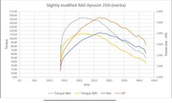
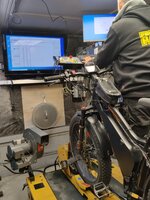
Dyno session is finally done 
Modified G062 motor running 60v (16s) 90A Battery DC (114A 2-3sec peak).
Dyno run was done at (pratkapaja.fi) on DynoJet 250i inertia dyno.
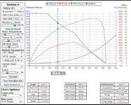
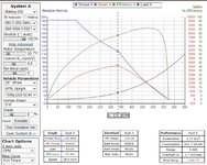
Because of dyno setting stall torque was not measured but run started at about 120rpm. As inertia dyno measures power output from which torque is calculated, motor low speed efficiency does not enable low rpm stall torque measurement. Stall torque can be estimated though to be in close agreement with Grin motor simulator that estimates the value to be approx 190nm.
In all Grin simulator predicts very close to true measured figures in area where both data are available.
Measured input power 5418w
Motor simulator estimate 5285w
Measured output 4042w
Motor simulator estimate 4092w
Measured torque at 215rpm 154,4Nm
Motor simulator torque at 215rpm 153,6Nm
Modified G062 motor running 60v (16s) 90A Battery DC (114A 2-3sec peak).

Dyno run was done at (pratkapaja.fi) on DynoJet 250i inertia dyno.
Because of dyno setting stall torque was not measured but run started at about 120rpm. As inertia dyno measures power output from which torque is calculated, motor low speed efficiency does not enable low rpm stall torque measurement. Stall torque can be estimated though to be in close agreement with Grin motor simulator that estimates the value to be approx 190nm.
In all Grin simulator predicts very close to true measured figures in area where both data are available.
Measured input power 5418w
Motor simulator estimate 5285w
Measured output 4042w
Motor simulator estimate 4092w
Measured torque at 215rpm 154,4Nm
Motor simulator torque at 215rpm 153,6Nm
Attachments
-
 Screenshot_2024-01-05-16-41-34-48_a23b203fd3aafc6dcb84e438dda678b6.jpg294.9 KB · Views: 468
 -
 Screenshot_2024-01-05-16-41-59-92_a23b203fd3aafc6dcb84e438dda678b6.jpg373.1 KB · Views: 489
 -
 Screenshot_2024-01-05-16-42-16-41_a23b203fd3aafc6dcb84e438dda678b6.jpg371.5 KB · Views: 402
 -
 IMG_20240105_104537.jpg320.2 KB · Views: 406
 -
 IMG_20240105_103001.jpg546.1 KB · Views: 400
 -
 IMG_20240105_102527.jpg615.8 KB · Views: 422


Chargeride
Well-Known Member
Good grief, what an amazing application of inginuity for a problem probably no one asked  .
.
Incredible.
Next of course is a piped heated jacket.
.Incredible.
Next of course is a piped heated jacket.
Okay so the verdict on custom winding: No go.Hall sensor board delete- to increase airflow by 20%+ and reduce "hot spots" hidden behind the board
High Temp Insulation Varnish brushed on windings
Oversized Vent holes 2-3x larger than before on both sides
8-10ML ferrofluid on magnets
Custom Hub sinks re installed
22.7" OD tire (low gearing, but not too low, "optimal" gearing for 30mph and below @ 72v)
Stainless/Nylon gears with oversized Stainless Drive Key (5x5x12mm) standard is 5x5x10 low carbon
Stator is ready for new windings- internally coated with high temp insulation, just waiting on the 180c rated copper, I went with higher gauge .81 mm and will attempt the same cross sectional area as the 6t motor (7 strands @ .81), with higher temp coating, higher gauge and 7 turns. Will probably upgrade to 12awg phases as well. - Just waiting on the copper in the mail
Gonna test this out and see what difference it makes to winding temps, then the new wound motor after.
I tried 3 different wire sizes, oem ~.5mm, larger .65mm, and much larger .81mm. The larger wires dont wind as well, the OEM sizing seemed to work best.
The oem motors are tightly wound, they seem to be wound very well. Atleast with my winding skills, I was not able to fit any more copper than the OEM motors come with. Additionally, I tried drilling out the stator. I tried drilling out the stator with diamond grinding bits. I tried using an angle grinder and dremel to widen the stator gaps to fit more copper. None of it helped much, and it damaged the laminations in the process. I also had significant issues with stator shorts when winding, especially when trying to cram in more copper.
I was able to wind a couple successful motors, but they are approximately the same spec as OEM, no improvements.
Pretty much what Justin (Grin) said about these windings. The new style stator on G063 looks bit more favorable in this sense.Okay so the verdict on custom winding: No go.
I tried 3 different wire sizes, oem ~.5mm, larger .65mm, and much larger .81mm. The larger wires dont wind as well, the OEM sizing seemed to work best.
The oem motors are tightly wound, they seem to be wound very well. Atleast with my winding skills, I was not able to fit any more copper than the OEM motors come with. Additionally, I tried drilling out the stator. I tried drilling out the stator with diamond grinding bits. I tried using an angle grinder and dremel to widen the stator gaps to fit more copper. None of it helped much, and it damaged the laminations in the process. I also had significant issues with stator shorts when winding, especially when trying to cram in more copper.
I was able to wind a couple successful motors, but they are approximately the same spec as OEM, no improvements.
Btw what type of damage you got on the laminations?
Did Justin do a writeup on this motor, if so I totally missed it, got a link by chance?Pretty much what Justin (Grin) said about these windings. The new style stator on G063 looks bit more favorable in this sense.
Btw what type of damage you got on the laminations?
Good info on the G063- I'll have to take a look at some pics again. The copper fill from the pics that I have seen looked weak, I'll take another look.
Laminations- All kinds of damage. Drilling (even with a smooth diamond bit) x 18 slots, the vibrations separate the laminations making them much thicker. The motor only has a tiny bit of clearance on each side between the covers and it reduces the clearance. Enough vibrations actually separate the laminations where they can split and fall off entirely as well, losing some of the laminations. Dremels, Angle Grinder also do the same thing with vibrations. All of the tools also seem to burr/nick/bend the laminations or unintentionally make it have sharp edges making stator shorts more common. A professional machine shop could probably do a better job, but I tried on 2 or 3 different stators and didnt have particularly good results either way.
New MXUS GDR19-FAT is here- I'll be testing out this motor starting today on the other thread!
Chargeride
Well-Known Member
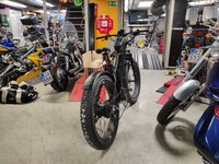
The go62 powered BMX is nearing completion.


Bella-Motor-HP
Active Member
- Region
- USA
Hello guys.
I have a G062 on the way and I plan to modify / rewind / rebuild the motor.
Great News.
I am a professional CNC Programmer / Machinist with access to a Brand New CNC Mill and also a brand new CNC Lathe with live tooling and a sub spindle.
So yes....I can make just about anything. I do it for a living. 30+ years now.
I want to rewind the stator with heavier wire like you tried.
I have a plan to machine the slots in the stator larger if needed.
The question is what effect will increasing the slot size on the laminations have to the motor.
There are specific formula to calculate what the dimensions should be.
Is anyone here a BLDC designer?
If so then give me the specs to build the best motor possible out of the G062 and I will make it happen.
Other than that my plan is to follow the proper procedures for designing a BLDC.
The motor design can then be modeled in ANSYS simulation software.
This verifies the BLDC design and allows for the proper tweaks to get the motor perfect.
So the stator is the component I need dimensions to manufacture / modify.
I can modify everything needed including the cases, the clutch , the shaft. I am going to make a shaft from 17-4 PH Stainless Steel.
Very tough Very strong material.
Then I can machine a larger hole for larges phase wires and maintain the strength of the shaft.
Depending on the thickness of the case and the size of the Rotor I believe it may be possible to open up the case bore and make a larger diameter rotor to install higher grade thicker magnets. Then i would machine the magnets and the outer stator diameter to precision dimensions allowing the air gap to be reduced if that helps.
I am more of a mechanical engineer. Electric is not totally new but not my profession.
Knowing that I can machine anything, what do you guys recommend?
Chargeride
Well-Known Member
Are you keeping the halls, because without them you could get thicker wires in there anyway, also possibly run fibreglass insulated ones without the sheath.
Chargeride
Well-Known Member
I hve just swapped the motor from my fatbike to the bmx, I rewired it ages ago and the case has ground down the phase wire to half size!!
Worked perfectly though
In fact its been rubbing on two of them....how did it run?

Worked perfectly though
In fact its been rubbing on two of them....how did it run?
Bella-Motor-HP
Active Member
- Region
- USA
PS.
If anyone has any burned up motors / stators of any kind for e-bike Hub Motors !!! Donate them to Research !!!
I only have limited amount of cash to throw at this project. Speed of completion depends on how my funds go.
I plan to run 1 G062 ON THE FRONT AND 1 G062 ON THE BACK.
(both modified) Run at 72v.
If I can get phaserunners I will run duel phaserunners but it looks like only the baserunner is available so I most likely will be running 2 baserunners and doing some throttle mapping. Also I plan to run 3x52V shark batteries, each battery is going to be stepped down to 24V and then run in series to output a constant 72v regardless of the batteries state of charge. In other words from a Fresh Charge until Dead I will have a constant 72V supply. So all in all I have roughly another $2000 to spend before i will have all that. So if i can research on motors that are already destroyed and you don't wanna fix it that saves me cash to put to the good stuff.
In return
I will measure all the parts that make the motors and draw 3D models / make blueprints for the parts.
Then we can reverse engineer any motor you send me, compare differences, make replacement parts, and test different stator configurations.
It will benefit the whole community.
I will pay shipping, and possibly we could work out trade deals for parts you need.
Like a solid clutch machined from SS Billet. Gears made from PEEK? Copper? Brass? Bronze? (whatever is quiet and strong enough)
Axels with holes out both ends and larger holes to allow larger gauge phase leads. Im thinking 2 phase leads out 1 side and the 3rd phase lead plus the hall wires, speed sensor, and temp sensor out the other side. That will allow for heavy gauge leads.
IDK
I'm open to suggestion
Bella-Motor-HP
Active Member
- Region
- USA
I do plan to keep the Halls.
I can machine extra clearance in the case or make a completely new case.
Soon as I get the G062 I will be disassembling it, measuring everything within .0001 of an inch (.00254 mm).
Then I will 3D Model every component and build a 3D assembly.
Next the stator model can be put into the ANSYS software and simulated to see exactly what we have.
Then changes we think we want to make we can input into ANSYS and see what the result is.
At that point we will be able to see the exact clearances we have to work with and decide what we want to modify.
I can actually draw the wire going around each stator tooth to make sure it fits. In stead of guessing. My guess is that the length of the stator tooth slot can be increased to incorporate more turns of wire. I'm not sure we want more turns. That produces more torque but less top speed. I'm looking for a top speed of around 45 MPH @ 72V with no problems going up a steep grade. If we make the stator teeth thinner (wider slot) we can fit more wire. But without running a simulation in ANSYS who knows exactly what the effect will be. I want to get good simulation results that agree with the goal we are trying to accomplish. Then manufacture the parts to test it. If all goes well we could very well end up with a Hub Motor MADE IN THE USA. It will not be cheap but it will be top quality made out of the highest grade of materials possible. So although expensive it will be built to meet our specific desires and last a lifetime.
I would not try this project.I do plan to keep the Halls.
I can machine extra clearance in the case or make a completely new case.
Soon as I get the G062 I will be disassembling it, measuring everything within .0001 of an inch (.00254 mm).
Then I will 3D Model every component and build a 3D assembly.
Next the stator model can be put into the ANSYS software and simulated to see exactly what we have.
Then changes we think we want to make we can input into ANSYS and see what the result is.
At that point we will be able to see the exact clearances we have to work with and decide what we want to modify.
I can actually draw the wire going around each stator tooth to make sure it fits. In stead of guessing. My guess is that the length of the stator tooth slot can be increased to incorporate more turns of wire. I'm not sure we want more turns. That produces more torque but less top speed. I'm looking for a top speed of around 45 MPH @ 72V with no problems going up a steep grade. If we make the stator teeth thinner (wider slot) we can fit more wire. But without running a simulation in ANSYS who knows exactly what the effect will be. I want to get good simulation results that agree with the goal we are trying to accomplish. Then manufacture the parts to test it. If all goes well we could very well end up with a Hub Motor MADE IN THE USA. It will not be cheap but it will be top quality made out of the highest grade of materials possible. So although expensive it will be built to meet our specific desires and last a lifetime.
You will need to machine the stator to fit more wire. I would not recommend a higher gauge wire, I would recommend .5mm wire and just more of them, like 25 strands instead of 15 strands. Machining the stator can damage the laminations in several ways, they can split apart, they can become rough which will short the wires when winding them, and the heat generated from machining can damage the insulation between laminations. Also when machining laminations you will have less stator mass, and smaller coils which is a negative effect. The motor also has very tight tolerances, when cramming more wire in there its hard to fit the hall sensor board and still have clearance between the motor case. Running high power (torque) I have also broken several G062 clutches themselves, not only the drive keys and gears, but the actual clutch as well.
The MXUS GDR19Fat is a more powerful motor, it has a stronger axle, room to fit larger phase wires, and is mechanically stronger gears/clutch. The downside to that motor is because its a BLDC it has issues pairing with sinewave controllers and ERPM issues.
I ended up going with a QS205 50H instead of messing around with these G062's.
Bella-Motor-HP
Active Member
- Region
- USA
I totally agree with you.
The G062 is just for a baseline design.
I want to build my own motor design.
But I want it to fit inside the stock G062 motor case so anyone who has a compatible case can just drop in the upgrade.
So right now I am developing the baseline parameters. And looking for advice from all of you based on your experiences.
Everything inside the motor is fairly easy for me to make. Other than the stator.
The stator really isn't a big issue. If it could be solid it would be super simple.
But I know it can't because of eddy currents.
Based off the Grin All-Axel Hub Motor (I assume they have a really good design they seem to know there stuff)
QUOTE
My main concern is the laminations. Those are .01378 inches thick. that is too thin to machine alone.
But if I clamp the plates together with a fixture I could easily machine them.
So how to you laminate the laminations?
Varnish Dip?
High Temp Epoxy Spray Paint?
Or just the glue in between laminations ? (what kind of glue?)
And what is the absolute best material to use for the laminations?
Again just to reiterate, I can and will make the tooling and fixtures required to assemble the stack.
I want to have the Best of the Best of the Best. And I find making my own stuff gets me there. And I love this hobby.
Another easier option may be to find a stock lamination stack at a lamination manufacturer that has enough material on it to machine it to my own specification?
Trust me. I can machine the stack without heat damage or pulling it apart. I got a half million dollar machine to do it with and the proper tooling and the proper knowledge.
I simply need to know What to Make.
The G062 is just for a baseline design.
I want to build my own motor design.
But I want it to fit inside the stock G062 motor case so anyone who has a compatible case can just drop in the upgrade.
So right now I am developing the baseline parameters. And looking for advice from all of you based on your experiences.
Everything inside the motor is fairly easy for me to make. Other than the stator.
The stator really isn't a big issue. If it could be solid it would be super simple.
But I know it can't because of eddy currents.
Based off the Grin All-Axel Hub Motor (I assume they have a really good design they seem to know there stuff)
QUOTE
- 0.35mm Laminations for low motor drag when pedaling unassisted
- Thermistor Beta: The 10K NTC thermistor has been changed from one with a 3950 Beta constant to a 3450 Beta constant. This allows for better resolution and accuracy when measuring high motor temperatures, as there is a more discernable voltage change.
- updated from N35 to N40 grade magnets. Stronger magnets allow the motor to produce more torque for hill climbing with less heat loss, but they also increase the drag of the motor when riding without power
My main concern is the laminations. Those are .01378 inches thick. that is too thin to machine alone.
But if I clamp the plates together with a fixture I could easily machine them.
So how to you laminate the laminations?
Varnish Dip?
High Temp Epoxy Spray Paint?
Or just the glue in between laminations ? (what kind of glue?)
And what is the absolute best material to use for the laminations?
Again just to reiterate, I can and will make the tooling and fixtures required to assemble the stack.
I want to have the Best of the Best of the Best. And I find making my own stuff gets me there. And I love this hobby.
Another easier option may be to find a stock lamination stack at a lamination manufacturer that has enough material on it to machine it to my own specification?
Trust me. I can machine the stack without heat damage or pulling it apart. I got a half million dollar machine to do it with and the proper tooling and the proper knowledge.
I simply need to know What to Make.
Bella-Motor-HP
Active Member
- Region
- USA
This is the motor on the way.

- Bafang Hub Motor includes 1000w motor, wheel, spokes.
- works with 20x4in fat tire electric bike or bicycle
- Voltage (v) : 48V
Power (w): 1000W
Max Wheel Diameter (Inches): 20
Stator Stack Thickness: 110*30
Winding Turns: 6T
No-load Speed (rpm): 420+-15 rpm
No-load Current (A): <=2.5
Rated Rotor Speed (rpm): 350+-15
Rated Current (A):<=27.7
Rated Efficiency: >75% - Axle Threading: 32.5mm
- Max Torque (N.m): 80N.m
- Dropout: 10mm
- Dropout Width: 177 mm
There is no need for rewinding really. G062 with 06 windings have quite low resistance. Magnets are decent (except the gluing)and saturation current quite high.
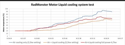
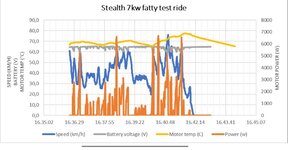
I'm running my modified G062 at 7000w peak (60v 120A battery current, 220A phase).
Torque 200++Nm. Stock windings, magnets and axle. Liquid and and air cooling. Also 8 awg phases etc.
I'm running my modified G062 at 7000w peak (60v 120A battery current, 220A phase).
Torque 200++Nm. Stock windings, magnets and axle. Liquid and and air cooling. Also 8 awg phases etc.
Attachments
Chargeride
Well-Known Member
I havent looked at this, how is phase current higher than battery current, is it lower voltage or different way of measuring it.
Similar threads
- Replies
- 9
- Views
- 4K
- Replies
- 11
- Views
- 1K
- Replies
- 7
- Views
- 4K
- Replies
- 19
- Views
- 3K