OkinawaJapan
New Member
- Region
- Asia
It seems the G63 is bafang's replacement for the G62. At some point in 2023 / 2024, the Ali Express listings switched over and the G62 was phasing out. In the g63 there were a number of incremental improvements - better jam nuts that are easier to remove, strong waterproofing glue (not easy to open!), the windings look cleaner and more consistent. I opened up a g63 at some point on my channel, and its on a bike I will ride this winter
I got the g63.1000 (5.5) with the red L1121 connector , its probably the easiest way to find it at a low price and have a good chance of it being an M14 axle. It may be difficult to find G62 with an M14 axle- I have heard RisunMotor had M14 axle g62's in the past.
If doing a dual motor setup, the g63.1000 with the 5.5 wind can be easily paired with the G61.1000 front fat motor thats also available in 5.5 wind. I had some stuttering problems with dual motors in VESC when the front and rear motor was a different winding.
but Yes, It would appear G62 is an endangered species! Potentially, not being manufactured by Bafang anymore.

Thanks for that. Yeah. Seems so.
I did have one reseller say they can custom order the 14mm G62 for me still.
And that link you provided for the G63 from PSR Ebike Store has been great on the communications. Better than all the others so far.
They even just said this:
"The motor is equipped with a temperature sensor, and the temperature sensor and the speed measurement line share a white line
bafang has now been upgraded to 1121 waterproof cables, which can provide a greater current"
That really true? Did you find that to be true for yours? It didn't seem so from the video that it was the case.
CONHISMOTOR Official Store are the ones that claim they can offer the G62 in a 14mm axle for me if I request it.
Risunmotor have been jerks to talk to. They say they have no 14mm axle versions for sale.
Seems that I'll probably go with a G063 from PSR Ebike Store and try to adapt it to my Baserunner L10 or Z9 to mux the speed and temp on the same pin. Just need to figure out which pin that is and find the pinout diagram for both. Edit: Seems it's the white pin listed in the diagram below.
Man, I really want to believe it already has a temp sensor built in. That would make the G63 the way to go nowadays.
$233 delivered is low enough to be worth playing around with.
Edit: They just shared this pinout diagram:
Great customer service from this guy for me today.
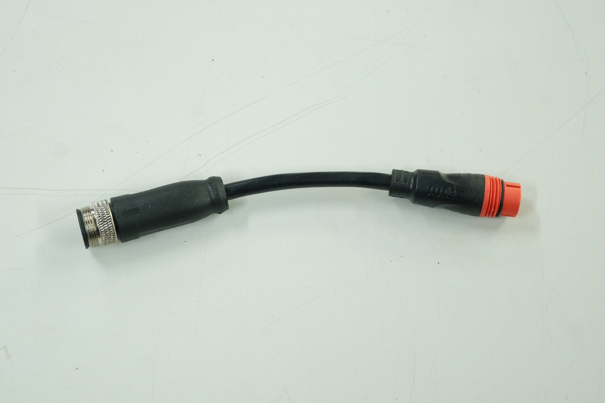
They say they provide the other end of the cable so I can adapt it as I need. However I really wished there was an L1019 to L1121 adapter cable. I'll have to research that and see.
Last edited: