Wired Cruiser - monster truck of ebikes.

There was a white pasty substance that looked like permatex teflon paste used to seal water pipe threads between the controller and mount,.. Another fella said it was used to transfer heat to the frame from controller.

It's most likely heatsink plaster,..

20250920_084054.jpg


It's specifically designed to conduct heat but Not electricity.

Most things that transfer heat also conduct electricity.
The plaster is safe to use to remove heat without shorting out any wires or conductors.

They also have heat transfer tape and different colored heat transfer "grease".

I also ordered some silicone heatsink glue to glue things in place, but I was sent the same type of paste. It doesn't cure and harden up like I was expecting.
 
It's most likely heatsink plaster,..

View attachment 199736

It's specifically designed to conduct heat but Not electricity.

Most things that transfer heat also conduct electricity.
The plaster is safe to use to remove heat without shorting out any wires or conductors.

They also have heat transfer tape and different colored heat transfer "grease".

I also ordered some silicone heatsink glue to glue things in place, but I was sent the same type of paste. It doesn't cure and harden up like I was expecting.
Ah. That is what it was then. Thanks for the info! I wasn't aware there was such a thing. Looking at the thermal conductivity of that stuff is like .671-4.8 w/m-k. Copper is 385-397 w/m-k and aluminum is 205!
 
Last edited:
Ah. That is what it was then. Thanks for the info! I wasn't aware there was such a thing. Looking at the thermal conductivity of that stuff is like .671-4.8 w/m-k. Copper is 385-397 w/m-k and aluminum is 205!

So it looks like copper and aluminum conduct heat better, but you would still want heat sink paste between the mating surfaces so the heat can transfer between the surfaces.
You don't want any air gaps between the two surfaces.

They use it on CPU chips in computers and on aluminum heat sink fins for power transistors.


The original controller on my first ebike was fully potted, and they used the heat sink paste between the 9 Mosfets and the aluminum heat sink.

Screenshot_20250920_103731_Gallery.jpg
Screenshot_20250920_103648_Gallery.jpg


The replacement KT controller only used a high heat plastic strip between the Mosfets and the aluminum heat sink.
The plastic isolates each Mosfet electrically, but doesn't conduct heat to the heat sink nearly as well.
 
The aluminum and copper antiseize comes in a paste, it would fill any voids between the two surfaces. The heatsink paste in comparison would act as an isolator. The only reason they use the heatsink paste is it doesn't conduct electricity, on the bike where the controller mounts, the screws from the frame into the controller kind of negate isolating the box with heatsink paste. Removing any paint between the two surfaces might be a consideration also. They want the controller to dissipate heat and it has fins, yet they either powder coat it or paint it, which is an insulator, doesn't make sense if it is that important.
 
I did some searching,..


Screenshot_20250920_132058_DuckDuckGo.jpg


Screenshot_20250920_132141_DuckDuckGo.jpg


Screenshot_20250920_132501_Adobe Acrobat.jpg


So yeah,..
If you're sure that you aren't going to short anything out electrically, Copper Anti-seize would conduct heat Way Better than thermal conducting paste.


Here's what the AI Robot has to say about it. 😁


Screenshot_20250920_133614_DuckDuckGo.jpg


You don't want to be doing this,..

Screenshot_20250920_134403_DuckDuckGo.jpg


Or this, with copper Anti-seize,..

Screenshot_20250920_134423_DuckDuckGo.jpg
 
Interesting, thanks for the info. Hadn't thought to google it. Just finished putting it all back together, the more times I do this the better I am at getting the wiring routed better and in the right places. I did use the copper paste, don't know if it is going to make a whole lot of difference, the bottom of the controller is anodized and it wasn't coming off with the effort I put in, but the inside of the box was bare aluminum.
 
Interesting, thanks for the info. Hadn't thought to google it. Just finished putting it all back together, the more times I do this the better I am at getting the wiring routed better and in the right places. I did use the copper paste, don't know if it is going to make a whole lot of difference, the bottom of the controller is anodized and it wasn't coming off with the effort I put in, but the inside of the box was bare aluminum.

If your controller isn't potted, then spray it down inside with AFC-50 or something.
I used the Canadian Krown version to hose down the guts of my controller.
It's thicker and more goopy.

The Fancy AFC-50 is for air force pilots who spilt coffee on the dash of their Jet Fighters,.
I was trying to protect a brand new circuit board, not fix a dirty one.


20250920_145445.jpg


Both my ebikes had fully potted controllers, but the KT controller wasn't potted.

Screenshot_20250920_144233_Gallery.jpg
Screenshot_20250920_144239_Gallery.jpg


I drilled tiny weep holes in the bottom corners of both the controller box, and the plastic container box to weep any water out from inside.

Screenshot_20250920_143829_Gallery.jpg
Screenshot_20250920_143931_Gallery.jpg
Screenshot_20250920_143947_Gallery.jpg
Screenshot_20250920_144022_Gallery.jpg
 
Ciphering more on the throttle settings, I had the throttle delay set to slowest, there are 0-3 settings, the book says start strength and I was trying to soften the departure kickoff, it is actually throttle delay. Set it to 0, no delay, and it is normal throttle operation.

There is a throttle follow setting, yes/no. In NO, the throttle is pretty much an on/off switch, in YES the throttle will follow the settings in PAS/PWM. In PAS, there is either 0-3, 0-5, 0-7, 0-9, corresponding to number of PWM levels within each choice. These PWM levels can each be set to whatever percentage of motor power that is going to be used at the throttle. So if 0-5 is being used, 0 would be softest start, 5 would be very abrupt is corresponding settings are set to 100% of motor usage. I thought PAS settings would be used in pedaling only, but they dictate the throttle characteristic also.

Got to ride on some crushed asphalt trails today, those 4" tires are the bees knees in loose stuff. And I am convinced this bike has enough power to climb anything a person is brave enough to ride up.
 
Did a scale of the Warrior. Total weight was 142#, 51.4 front and 90.6 rear. With myself on the bike, total weight was 322#, 107 front and 215 rear, me weighing 180#. So the tires rated at 198# max, the rear is overloaded.
 
Wonder how the balancer works for charging or is it just for depletion of the batteries. The front battery is 20 Ah the rear is 15 Ah, both chargers are 3.5. Are the batteries separate on the charging circuit so they don't see each other or does the balancer come into play.
 
Wonder how the balancer works for charging or is it just for depletion of the batteries.


Check out this link,..


Battery Balancers are used to start fires. 🔥

Keep an eye on that thing and don't start it on fire.
 
Well thanks for that read. My balancer looks like the one in Ravi's first post that he is looking at. I am charging right now, it doesn't mix the charge. One battery just went 100% and the other is still at 95%. That last 5% takes forever, then the amp draw drops to 4 or 5 which is noncharging draw and the green light comes on. I may just use one battery, have to see how the discharge goes. Haven't heard any of the Wired community burning anything down yet, there'd be a big outcry if there was. Thanks for the read.
 
Had the rear tire off to change out the brake disc. That was a no go, the 220 floating rotor buttons that are between the mount and disc interfered with the motor, have to get a regular flat disc. Hope it is flat. Also was going to remove the cover on the motor, those torx bolts are very tight. Was using an impact driver with hammer and the torx bit twisted. Ordered some S2 hardened steel pieces and going to put some heat to them on the next try.
 
I worked on a bike like this last month. Stopping distance from 20 mph was 120 feet. It was 98.4 pounds with mechanical brakes. One local shop quoted $740 to install four piston hydro. I did it for a lot less and that was the braking fix.
 
Looking for a tool to pull this cassette off. Think this is the ring that needs to be removed. It is 6 prong, can't find any. About 1.3" i.d. at the inner prong cutout.

View attachment 200406
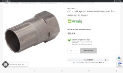
I'm not positive but I think that's a freewheel not a cassette
If so the removal tool fits down the center.
Screenshot_20251004_211926_Chrome.jpg

The outer 6 dimple ring is part of the assembly
Screenshot_20251004_212355_Chrome.jpg
 
I worked on a bike like this last month. Stopping distance from 20 mph was 120 feet. It was 98.4 pounds with mechanical brakes. One local shop quoted $740 to install four piston hydro. I did it for a lot less and that was the braking fix.
The stock 203 brakes are pretty good. I installed 220 disc on the front and gonna put same on rear. Fixing some of the Chinese engineering at the moment. Took a file to the axle, it is soft, don’t think there is any hardening done to it. The threads into the frame are disappointing.
 
Back