what sinewave controller can i use to replace the controller i have with the correct connections

Your C965 and P850 don't have the same connector? In post #18, you show a picture of a flat connector. If you want advice on how to reconnect, you should clarify what's going on here. THere's battery power in the display cable and if you route it incorrectly. you will either blow up the display or melt down the battery (subject toi any fusing).
 
hi,
yes they have both the green round 5 pin may i correct myself the c965 has the green 5pin male connection where as the p850c has the green round 5 pin female hence i had to buy and extender cable with both 5 pin male on each end as the cable coming from the controller to the green 5 pin connector is also female i will place a photo of my p850c display's plug. that is my plug on my p850c display and my battery has a fuse which you will see just below the sticker is the fuse housing
 

Attachments

  • P850c plug 5 pin female.jpg
    P850c plug 5 pin female.jpg
    101.3 KB · Views: 148
  • 20220528_194056.jpg
    20220528_194056.jpg
    194 KB · Views: 147
also to add i have a blue round 4 pin connector but that's for the power on/off and settings controller for the display
 
forgot to add, if you look at this photo and zoom in on the the controller you will see the 5 coloured wires : red,blue,green,yellow and black comming from a block connection which is my display cable feed running through the frame of my bike to where the display connects. as i have marked out with three red pointers 1 being shown where he is connected from the controller and the other 2 where it is feeding away heading towards the frame
 

Attachments

  • 20220528_192528.jpg
    20220528_192528.jpg
    199.2 KB · Views: 132
I don't know if you've run into this yet, but you should know the wire colors are NOT standardized. Sometimes you can get a general idea (like black and red for example) but you really need to consider them for what they do, not what color they are. The green, yellow, blue, wires are another example of wires with known uses (the phase and sensor wires) but even that knowledge will do you little good. This because there is no guarantee that the yellow motor wire will connect to the yellow controller wire.

My experience has been that USUALLY, when considering the round plugs, the pin position within the plug can be trusted, but are still worth the trouble to confirm.

My point is the colors of the wires leading from your display cannot be trusted to carry any certain function. FAR more effective, is to consider what each wire does.....

Further, when it comes to the display and controller, different manf's us different "languages" to exchange information on the data line from the display to the controller. I bring this up because even if you get the display to light up with the correct wiring sequence, that display may still be an issue if it's not speaking in a language the controller understands.

Sorry, not trying to poop in your Cheerios or be Debby Downer, just trying to point out what you are up against here.
 
hi , i understand what your saying and i totally agree. what gets me is the old display wiring c965 has different colours well say a couple at least are different and can be confusing as you said if not known what each wire does. however i did find some things out of interest if this even will help? i will attach images
 

Attachments

  • 7UcYQd8.jpg
    7UcYQd8.jpg
    16.6 KB · Views: 228
  • BBSxx.wiring.image_5494.png
    BBSxx.wiring.image_5494.png
    195.6 KB · Views: 176
OK. So the connector on your controller has a round 5 pin connector with female pins, while the C965 has male pins. That's the opposite of the BBS02/BBSHD diagrams floating around in the above posts. I posted one too. As far as colors, this is all from diagrams or have you looked inside the displays to see what colors were actually used?

Another question. You can plug the C965 back in and it still works? If so, good. Nothing had been blown up.

The answer that comes to mind is that a straight thru male-male adapter cable doesn't work because the pins are mirrored. I wouldn't un-mirror them until I first verified where the voltage and ground actually are placed on the round controller connector. Then maybe look at the wire colors inside the displays. When playing with battery power, always verify.
 
hi yes i opened up my c965 display and and the colours as shown are red,blue,green,yellow and black.
i can plug my c965 display back in and works as normal no problems
hence the p850c display is another colour type wires different to the c965 =brown,orange,green,yellow,black -= p850c display colours and i hadd to order a cabl;e with 5 pind round green connector male to male to be able to connect p850c display to my main leading wird for the display from my e-bike.. i hope this helps
 
The match would be red-brown, blue-orange, yellow-yellow, green-green, and black-black. What I would do is open the P850C and trace each color to a specific pin, using a continuity tester. It may turn out that a straight-thru adapter won't work.
 
hi, i will take a look today and do this test, hopefully i will be able to come back with a positive answer.. i'll keep you updated.
 
The match would be red-brown, blue-orange, yellow-yellow, green-green, and black-black. What I would do is open the P850C and trace each color to a specific pin, using a continuity tester. It may turn out that a straight-thru adapter won't work.
one more thing as you mentioned using a continuity tester? would there be power to the p850c display needed in order to do this or just a straight forward test?
 
ok continuity test done on each pin to the corresponding colour of wire inside the p850c display.. the findings are as follows......
pin 1 = orange
pin 2 = white
pin 3 = brown
pin 4 = blue
pin 5 = black

i hope that with this information will be useful in hoping that i can wire correctly and be able to use my new p850c display on my existing connection on my e-bike. will wait for reply
 
here is the display wiring diagram but mine has a white wire instead of black but i think this will give an idea as to where each wire goes and what its job in hand is. image attached. bearing in mind that colour of wires shown here differ to mine in my p850c display..
 

Attachments

  • c965 display wiring.jpg
    c965 display wiring.jpg
    148.2 KB · Views: 178
  • p850c wiring diagram.jpg
    p850c wiring diagram.jpg
    176.9 KB · Views: 175
hi what i can do in a bit is remove my display i have now and make a photo of it with the connection plug, also will do a continuity test on that display too, but as for the continuity test on my controller i think that would be a bit difficult but i can certainly make a photo of my display and connector and put the results of the test with the colour wires and pin count and put them here as what i did with the p850c display. hopefully fingers crossed may be able to get him to work and communicate with my bike.
 
hi . ive done the continuity test on my display (c965) and also taken photos on my display with connections both from display and leading from my controller to the display. As you will see the the connection from my display is male, where the connection from my controller that my display connects to is female. i will also add from the test pin numbers and wire colours.

pin 1 = blue
pin 2 = green
pin 3 = yellow
pin 4 = black
pin 5 = red
thats the order of wires from pin to location within my c965 display.

image 1 = connection from controller = female
image 2 = connection from display(c965) = male
image 3 = my display
image 4 = on/off functions remote panel.

i hope that information will help and maybe, just maybe be able to fix this so my p850c display will work on my e-bike.

will await for replies
thanks
 

Attachments

  • 20220604_115041.jpg
    20220604_115041.jpg
    142.1 KB · Views: 137
  • 20220604_115038.jpg
    20220604_115038.jpg
    166.2 KB · Views: 125
  • 20220604_115032.jpg
    20220604_115032.jpg
    120.7 KB · Views: 130
  • 20220604_115023.jpg
    20220604_115023.jpg
    126 KB · Views: 122
hi this is my conformation that what test i did this morning on my current display is correct with this diagram. i will post both male connection and female connection, however as you have seen from my p850c display the colours of the corresponding wires differ than my c965 display.
 

Attachments

  • wiring colours to confirm my contiuity test on my old display.jpg
    wiring colours to confirm my contiuity test on my old display.jpg
    40.3 KB · Views: 165
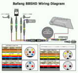
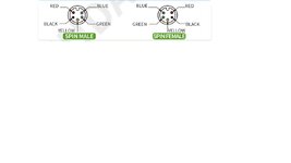
Well, all that info is really good. It seems that your C965 follows the standard used for many displays that plug into external controllers. Female socket on controller, and male pins on display connector, This is for the KT LCD3, a different manufacturer, but they're quite popular too,

LCD3_jumper.jpg


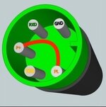
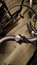
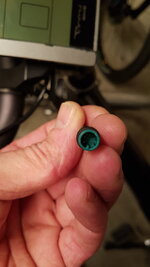
But for their middrive motors, Bafang switched to their own scheme, using a male pin on the controller end, which you don't have, and a female socket on the display. Here's your picture. I trust I followed the same order?

1_aaa.jpg

It's way different from what I though it was. I don't think your adapter cable damaged the P850C, but you'll have to see.

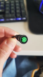
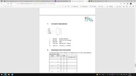
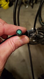
I'd suggest you do one more thing first. Looking at the C965 connector, with the notch at 12-0-clock, I believe you're picking pin 1 as the pin at 11-o-clock? Since you've referenced pin 1 on the C965 as blue, please go to the controller connector and careful check the voltage across pins 5 and 4. That should be your battery voltage. AFter that's verified, then you're pretty sure the wire order is correct.

Then you can cut the adapter cable and rescramble the wires, or you can cut the connector off it and wire it to the P850 after cutting off its connector. That would preclude its use on a future bafang middrive.

There's just one issue. Hopefully the firmware in the P850 is capable of talking to the old controller.

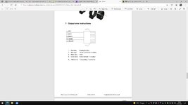
Let's see what your proposed wiring will look like.
 
hi,
when i got the extension cable with the two male plug's on each end and connected to my bike and powered up my bike then tried to power up the p850c not thing happened, and for the order i looked through a magnifying glass and the connector which i saw how it was numbered being 1 the 2 as nothing then 3 4 being the same as 2 then 5 , so if worked out it would run as 1,3,5 as numbered leaving 2,4 blank, obviously if this is done correctly as you mention then surely once connected back onto my bike i should at least then get power to my new display right. and i will put an image up maybe this would be good to make the new cable for the p850c display as i already have a male 5pin connectors. i will also add more thing i did a bit of research into the p850c display before buying it and this was my response. i will also add that, by all means take a read and you will see that even its been confirmed that it will work against my motor. and regarding to the test on my controller cable? use a test meter against pins 4- 5 yes? i will await for more input
 

Attachments

  • confirmation that display will work with my motor also confirmed with technian.txt
    627 bytes · Views: 160
  • _16e4a_display_kabel.jpg
    _16e4a_display_kabel.jpg
    263.9 KB · Views: 133
just another thing as i would imagine that this would be my controller so to speak well similar but connections would be the same except mine as one extra for battery which i will put an image of what i have on my e-bike, but this should once all is correctly wired in prospective as to how the layout is for my c965 display, my p850c should work with my controller?

image 1 = is my actual controller i have in my bike
image 2 = is the kt series controller, however connections are as good as the same as mine , but as i point out mine has an extra connection with metal blade pins, which are for interlocking with my battery pack
image 3 = my battery with the interlocking connector
 

Attachments

  • controller.jpg
    controller.jpg
    53.9 KB · Views: 120
  • KT Series Controller.jpeg
    KT Series Controller.jpeg
    95.7 KB · Views: 127
  • 20220528_194056.jpg
    20220528_194056.jpg
    194 KB · Views: 124
Back