ebikeling 48v 35amp 1500watt modding to fit harness

Deke206

New Member
Hi, I'm a handy person who is in search for practical knowledge on a couple of intriguing things:

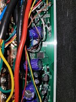
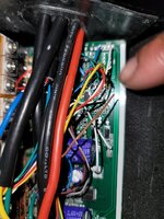
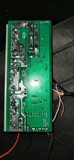
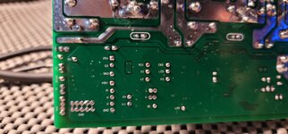
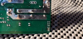
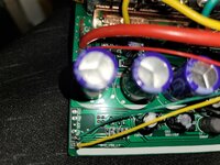
The first and for most item is a controller from ebikeling 48v 35a 1500watt. I am most interested in and wishing to learn is about the board itself what the noted points are for? How can I test them for certain functions e.g. throttle do I need a certain kind or can I match the colors to what I have and so on. I'm really capable of soldiering onto the points.

Hoping to find someone in W. Los Angeles to video chat while I'm working on it. I can afford a matching harness but I would like to learn about the points and what the functions are and how to diagnose the faults and the correct voltages. I'm tired of sifting through page after page of wiring diagrams that don't match my particular item and please save your stupid comments. I've also contacted ebikeling for a wiring diagram but it doesn't match there item. I said as much but they said its correct. Anyway, would greatly appreciate your knowledge and time in helping me get my ebike back on the road.
 

Attachments

  • 20201112_232133.jpg
    20201112_232133.jpg
    581.7 KB · Views: 1,208
  • 20201112_232339.jpg
    20201112_232339.jpg
    425.7 KB · Views: 688
  • 20201112_232414.jpg
    20201112_232414.jpg
    327.4 KB · Views: 1,662
  • 20201127_105847.jpg
    20201127_105847.jpg
    275.4 KB · Views: 829
  • 20201129_123755.jpg
    20201129_123755.jpg
    100.9 KB · Views: 596
  • 20201201_125851.jpg
    20201201_125851.jpg
    279.1 KB · Views: 766
  • 20201201_125910.jpg
    20201201_125910.jpg
    273.3 KB · Views: 699
I don't think many people have tried to match arbitrary printed wiring board pad names to generiic functions. It would seem each manufacturer uses their own names.

You might be in luck if you were looking for a particular function, like a speed sensor input and someone else with a board from the same maker has it on his bike and can tell you the pin names.

I have a couple of the ebikeling 500W controllers not in use, so if you somehow had all the wires pulled off on a sensor, I can tell you where they are connected on mine.
I would appreciate that but i don't know if that would suffice. But in retro spect that may work. So let me explain the details original throttle, pas sensor and bafang 750watt rear hub, two brakes front and rear and a light. My harness no pin out schematic just the ebikeling one. Need to match those items to the original harness.

Display ebikeling s830

Need to know what pins are the actual sensor, power and ground by voltmeter and matching the current wires.
 
Last edited:
My throttle: 3 wires red, black, and yellow.
Going to button on throttle orange one.

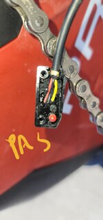
PAS Module and sensor: red, black and yellow.
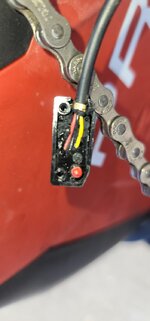
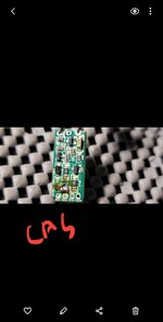
Module: had red, black yellow and orange (blown CAS sensor on original controller of which counted the magnets for smother peddle assist) .
New controller: no cas system.
Note:eek:riginal display wires removed to put the original harness matching julet connector for display with original harness.

PAS sensor wires: one 3 pin julet connector red, black, and yellow
 

Attachments

  • 20201202_234851.jpg
    20201202_234851.jpg
    105.5 KB · Views: 409
  • Screenshot_20201202-234638_Gallery.jpg
    Screenshot_20201202-234638_Gallery.jpg
    70.8 KB · Views: 378
Trying to understand here. Original ebikeline water proof harness with the 1500W controller. Changed to a different controller with a different harness. It doesn't have a cadence sensor?
 
No that is not correct. New ebikeling controller tryin to use with original harness from the bike. Cas sensor is on the original controller blown fuse on the cas sensor. I have pdf for wiring the ebikeling controller matching pins.

So far I haven't gotten anywhere. Right now, trying to figure out how the light gets turned on and how the PAS and throttle is wired. I have a white wire on the far right side giving off 53v and red wire giving off 4.7v and a purplish brown wire giving off 4.7v and white wire with 1:1 next to it giving off 5v.

What I have solved so far is the colors for my throttle 5v red wire, black wire ground, and yellow wire signal.

Harness has common ground for all devices except the light of which I just figured out just now.
 

Attachments

  • 20201203_214031[1].jpg
    20201203_214031[1].jpg
    416.9 KB · Views: 685
Thanks for your help but I got it.

EBIKELING 48V 35AMP 1500WATTS THROTTLE AND PAS MOD TO ORIGINAL BIKE HARNESS
BY MATCHING WIRES TO NODES NOTED ON THE BOARD.

NOTE: A VOLTAGE METER AND A PAPER CLIP WILL BE NEED ALSO A ROACH CLIP TO ATTACH LEADS TO WIRES

PAS: Red wire to 4.4V of the 5v nodes purplish wire
signal white wire or noted 1:1 on the board
Black ground wire to ground area on the board, lower right noted ground

Throttle: Red wire to 4.4v 1 of the 5v noted nodes on the board on the far right of the board,
Signal wire to node noted SD on the board just left of the 5v noted nodes on the right
Ground wire can go to noted area for ground or if your harness has the common ground for throttle and brakes then use that.

All other wires should go to there respected colors for motor and display.
Sure is smoky in here....pas the roach clip please .
 
Back