Custom E-Bike battery issues

Thanks for all your advice. Most manuals are not user-friendly and are loaded with technical jargon. I feel that manufacturers need to adopt a new approach to technical writing by including videos, images and animations to make it more understandable.

IMO Discussion forums like these and online videos are way better to learn stuff instead of reading those boring manuals. At the end of the day, it comes down to your style of learning.

I ordered the SkyRC balance charger with AC/DC input (IMAX B6-AC Charger/Discharger, 1-6 cells), and prepared a 13s2p, 48 volts Battery Pack with 18650 Li-Ion, 3.6 volts, 2200 mah cells of the same manufacturer. Once I get the balance charger, will measure and verify all the cells internal resistance match, before charging the cells.

I'll be using the battery pack with no BMS initially to check the range and make sure all the contacts and connections are fine in the battery pack. If I come across loose connections or contacts issue, I may have to solder the strips and bus bars. Not sure if anyone else using a battery kit have had to weld or solder. Once the contacts issue is sorted out, will add a compatible BMS.

Wish you all at EBR a Happy and Healthy 2021.
The 'no BMS' thing makes me nervous, even for a short time. Just sayin' 😔
 
The need for attention and presense of mind cannot be stressed enough.

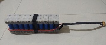
Some more goof-ups from me: I decided to build a 13s2p, 48 volts 4.4 ah battery made of same cell type (18650 Li-Ion, 3.6 volts, 2200 mah) and manufacturer. I contacted the manufacturer for the cell data sheet - didn't get one, however they mentioned the resistance is around 50 milli-Ohms per cell.

I was waiting for my SkyRC iMax B6AC version 2 to arrive (B6AC version 1 does not have the resistance meter), meanwhile I built the 13s2p, 48 volts 4.4 ah battery pack using the assembly kit, and decided to safely charge it to 54 volts using a generic 2 amp charger and a multimeter plugged in to monitor the voltage. Surprisingly, the 2 amp charger cut off when the multimeter read 53 volts.

Thankfully, I didn't use the battery pack, and once I received the balance charger, I had to remove the endcaps, busbars and strips to discharge the cells, since the openings on the endcaps are too tiny to fit in the banana plugs. I decided to discharge the cells to nominal voltage one at a time, strangely, a total of 8 cells out of the 26 were not detected by the balance charger discharge program, and when I checked the voltage with my multimeter, they read a shocking 4.4 volts.

Now I had to quickly find another way of discharging those cells. Initially I thought of ordering an smd led to discharge the cells, but later realised that I could use these cells as DC input to the same balance charger, so I hooked them up and let the balance charger discharge them to below 4.2 volts. And after all the 8 cells were discharged below 4.2 volts, now the balance charger discharge program detected those cells. 😅

After having discharged all the 26 cells to nominal voltage of 3.7 volts (3.6 volts would be ideal, but I wanted to keep them at 3.7 as a safer option.), I measured the resistance of all the cells which range from 43 - 70 milli-Ohms, which I guess should be fine?

I figured that there were contact issues which caused the voltage disparity between the cells earlier, and after careful observation the root cause is the alignment of the strips and the cells. I need to make sure the strips are straight and make good contact with the bus bars. The spacers and the cells need to be aligned as well, and to avoid disorientation of the spacers, I have decided to shrink wrap the pack before laying the strips and bus bars, and cutout the top and bottom part of the wrap to expose the cells terminals, and then lay down the strips and busbars, hammer the endcaps, check the alignment with a leveler and once all the connections are done, shrink wrap the battery pack twice to offer extra stability, and that's not all, I will be using foam in my frame bag to cushion the riding impact.

Hope everything works out well, for all the time and effort.
 
Last edited:
After having discharged all the 26 cells to nominal voltage of 3.7 volts (3.6 volts would be ideal, but I wanted to keep them at 3.7 as a safer option.), I measured the resistance of all the cells which range from 43 - 70 milli-Ohms, which I guess should be fine?
The 43-70 mOhm range is ~63% spread, quite a bit. As my post #24 in this thread states, variances of over 20% can adversary affect cell life by 40% or more. Higher resistance variances can lead to other issues.

Post #24 also has links and an MIT article download re this issue.
 
Thanks again for sharing the study. I had glanced over it earlier, but read it with more focus this time around.

An excerpt from the Study:

Thus, if the internal resistance of an individual cell has any effect on lifetime, it is much smaller than the effect of the internal resistance mismatch between cells connected in parallel.
Of course, such an effect might be of scientific interest and could be studied further, but the larger effect is of more engi- neering importance.
The spread in my battery pack for individual cells is actually just under 40% not 63%.

Now, as per the study to increase the lifetime of my battery pack, I need to match the cells in parallel such that the resistance spread is below 20%.

I checked the parallel pairs and found two mismatched pairs, luckily I need to interchange just one of them to match both the pairs.

Let me prepare the battery pack and start testing. I'm using the battery pack without a BMS for now, until I'm confident about the contacts and connections.
 
The spread in my battery pack for individual cells is actually just under 40% not 63%.
Going from 43 mOhm up to 70 mOhm is 63%. Going from 70mOhm down to 43mOhm is more like 40%, as you pointed out.

Statistics are a wonderful thing!

Be careful out there! 😎
 
Well, I guess I've been through all the mess possible while building a battery pack. My latest addition: The root cause of the contacts issue is that the spacers and the strips get mis-aligned after fixing the end-caps with a mallet hammer. While hammering the end-caps, some of the spacers drift downwards causing the crooked alignment.

So, while trying to align the 13s pack, I was using a metallic scale as a leveler which slipped and shorted 13 cells on one side and I wasn't wearing any gloves 🙄 The pack started fuming and with the tip of my fingers I pushed the pack around and the scale fell off. The entire incident took about 4-5 seconds, with the pack still fuming I put on the gloves and carried the pack to a safe place and dropped it on the lawn and rubbed the pack to douse the fumes.

All the fumes were gone in about 10 minutes, after which I opened the pack and isolated the faulty cells. A total of six cells had a leak of varying degree. I rebuilt the pack as a 10s battery, discharged each cell to nominal voltage, and this time around used a wooden block to level the pack and then charged it to 41volts. The only thing left now is taking it for a test ride.

Here is a pic of 3 cells which had a major leak. In summary the battery assembly kit I used works fine for small packs. The bigger and longer packs have stability and alignment issues. Maybe the latest version of Vruzend kit is a better bet, but I've always felt that the strips and bars are too open.
 

Attachments

  • IMG_20210128_190838104.jpg
    IMG_20210128_190838104.jpg
    189.5 KB · Views: 261
Haha these are not Lego packs that's for sure 😆 
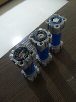
Now that I have built and dismantled the pack number of times, I've got a sense of its limits and the correct way to build the pack with the assembly kit. BTW the assembly kit and cells I used are locally made and are not renowned brands, but I'm really impressed with the quality.

The next time I build a new pack I'll follow the best practices learnt from my experiences. As a rule of thumb, I need to be gentle while hammering or maybe use a clamp, and always be mindful of the alignment so that I get it right on my first attempt without having to take it apart multiple times.

The 36 volts, 4.4 ah, 10s pack looks sturdy despite all the stress. Maybe will add a BMS if required in the future. I'll need to test the pack riding on a rough terrain to make sure the pack does not fall apart.
 

Attachments

  • IMG_20210207_200620477~2.jpg
    IMG_20210207_200620477~2.jpg
    163.5 KB · Views: 255
Last edited:
hammering the end-caps,
Not necessary. I have a version 1 vruzend 24V pack in use for two years.
I have built and dismantled the pack number of times,
Increasing stresses on the cells...
I always thought those no-weld Lego packs are problematic.
While there are caveats, dominantly inconsistent sizing between battery brands. There are many more successes than failures. Failure seems to be from fellas that just shouldn't mess with high power lithium batteries.
 
The assembly kit I used is not a Vruzend kit and the design is different. The spacers go on the cells first, and then you lay the strips and bus bars on the cell terminals, then you plug in the springs to the end caps and fix them on to the spacers.

Here is a link: Nishi Assembly Kit

The only stupid mess was using a metal scale to check the alignment, for some reason I was very negligent at that moment. I used a wooden one later, but now that I have all the required tools and the experience, my next attempt will be smooth with no mess.

I thank all the posters for guiding me and sharing your knowledge. Much appreciated. 🙌
 
Last edited:
Back