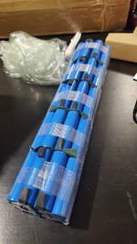
AliExpress battery

What do you think?
It's a good DIY kit to save money?

It's not only capacity, the possible current (Stromer operates with high amperage) is also important. And of course within a wide temperature range.

The Risk is tremendous: If the BMS does not properly recognize the SOC, the charger might overcharge the cells.

If you buy or build such a battery, charge it always far out of your flat (like in a fireproof flower pot)
 
The Risk is tremendous: If the BMS does not properly recognize the SOC, the charger might overcharge the cells.

This is not typically true unless the BMS is integrated with the charger.
In most battery-powered applications the BMS performs monitoring, reporting and emergency management. "Regular" charging is typically managed by the charger, itself. While I don't know the specifics, I do know that the Stromer battery is a 13S6P pack with an external charger. This pack has a nominal voltage of 48V and a fully-charged voltage of 54.6V (quite common for most Li-ion batteries of the last decade or so - though consumer products have been steadily ratcheting up that top-end voltage in search of ever higher capacity).
And as can be seen by the CR190 and CR245 chargers, the typical Stromer charge rate is either 3.5A or 4.5A, and I would guess that they use a very common CC-CV charge profile of either 3.5 or 4.5A up to a constant voltage of 54.6V.
So as long as these 3rd party batteries can handle 4.2V/cell, then they are very, very unlikely to overcharge.
A more likely risk is that the cells are not terribly well matched and the BMS will need to kick into action during charging when one cell rises above the other cells. While the charger has "analog" control of the charge current and voltage, the BMS typically has an on-off switch. If you hit the off switch while charging the pack won't fully charge (a safety precaution since one cell is getting too high).
Perhaps a greater issue is the same scenario on the discharge side - where, as you mention @bluecat the Stromer discharge currents are quite high. And there may be a slightly higher safety risk on that end, but more likely a performance issue ... if the Stromer BMS emergency disconnect per cell voltage is lower than what the 3rd party cell needs then cell damage is more likely to occur. Or if the 3rd party cells cannot handle the high discharge currents, then their voltage will drop rapidly - again, possibly causing the BMS to force a disconnect event.
The devil, as always, is in the details, but I would argue that these 3rd party packs are more likely to suffer performance issues than safety issues provided a Stromer BMS is still being used.
Now if the BMS is aftermarket, too, well then, that's a whole different story!
 
The devil, as always, is in the details, but I would argue that these 3rd party packs are more likely to suffer performance issues than safety issues provided a Stromer BMS is still being used.
Now if the BMS is aftermarket, too, well then, that's a whole different story!

Stromer uses the EnergyBus protocol for communication between charger and BMS. The protocol is open source - but this does not mean, it's free of charge. In fact, it would be extremely surprising for me, if any 3rd party retailer would offer batteries or chargers compliant with this protocol.
 
I've done it. After looking for options to replace the battery in my ST1, I found three common options...

- Buy new (crazy expensive)
- Have someone refurbish it for me (still pretty expensive)
- Buy cells and spot welder and try it on my own (cheaper but unknown learning curve involved)

I then saw the above mentioned battery, and given that it was much cheaper than the other three options, I thought "why not".

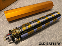
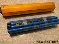
The "battery" comes as a pre-welded array of 50 cells. The cells are unmarked, so I'm not expecting Samsung quality, but my results have been quite good. In order to install this battery, you must first disassemble your existing battery and then remove the BMS from your existing battery. The BMS uses 9 battery monitoring wires which lead to tabs along the length of the battery. These must be unsoldered and resoldered to the new battery. Next are the two main power connectors. Lastly, there are a couple of temperature sensor probes. I transferred everything mentioned above to the new battery, After this, I reassembled it exactly as I took it apart, and it worked fine the first time I tried it.

When plugging it in the first time, I was a bit nervous so I charged the battery outside. I also monitored the temperature while it charged. I've had zero problem. The battery is rated at 540Wh, and real-world results seem pretty close to what you'd expect.
 

Attachments

  • battery1.png
    battery1.png
    1.9 MB · Views: 466
  • battery2.png
    battery2.png
    2 MB · Views: 448
Great! Im actually waiting for mine also... you did not document how you did it? How did you attached the bms to the new battery? I was wondering because the old one has holes for the bms to screw-in.
 
I took a few photos for my own reference, but there already exists a great documentation of a teardown here. The two black caps come off each end with some patient and gentle persuasion with a flat end screwdriver or two. Once the caps are removed, you can push on one end, and the innards come out in one piece. It must be reassembled in the same orientation, so I would recommend taking lots of photos as you go along.

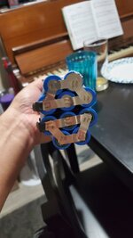
Pretty much everything went smoothly. Connecting these two main battery power connectors that you mentioned to the BMS was the only part of the process that I was not 100% happy with. There are two large flat metal tabs that come from the original battery and connect to the BMS as seen here. The tabs have a hole drilled near the end of each, and a screw fastens each of these tabs to a post on the BMS. The new battery has these same tabs, but they do not have holes drilled in them. My original thought was to simply drill holes in the tabs and attach them in the same fashion. When I actually got the battery in hand, I discovered that these tabs were about 1/2" shorter than they are on the original battery. They are not long enough to reach the posts on the BMS. What I ended up doing was to cut the tabs off of the old battery and solder them, face to face to the tabs on the new battery. This extended the length of the new tabs long enough to reach the posts, and the holes were already drilled. Ideally, this should have been done with a spot welder, but I paid special care to make sure that the connection was good and solid. I roughed up each connecting surface, and used an adequate quantity of flux. I also added enough shrink wrap to match how these tabs look in the original photo above.
 
Last edited:
I took a few photos for my own reference, but there already exists a great documentation of a teardown here. The two black caps come off each end with some patient and gentle persuasion with a flat end screwdriver or two. Once the caps are removed, you can push on one end, and it innards some out in one piece. It must be reassembled in the same orientation, so I would recommend taking lots of photos as you go along. Pretty much everything went smoothly. Connecting these two main battery power connectors that you mentioned to the BMS was the only part of the process that I was not 100% happy with. There are two large flat metal tabs that come from the original battery and connect to the BMS as seen here. The tabs have a hole drilled near the end of each, and a screw fastens each of these tabs to a post on the BMS.
The new battery has these same tabs, but they do not have holes drilled in them. My original thought was to simply drill holes in the tabs and attach them in the same fashion. When I actually got the battery in hand, I discovered that these tabs were about 1/2" shorter than they are on the original battery. They are not long enough to reach the posts on the BMS. What I ended up doing was to cut the tabs off of the old battery and solder them, face to face to the tabs on the new battery. This extended the length of the new tabs long enough to reach the posts, and the holes were already drilled. Ideally, this should have been done with a spot welder, but I paid special care to make sure that the connection was good and solid. I roughed up each connecting surface, and used an adequate quantity of flux. I also added enough shrink wrap to match how these tabs look in the original photo above.
The new pack assembly looks good... Well done!
 
Last edited:
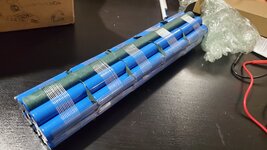
I got my battery, ordered from aliexpress also... but darn im disapointed its unlike what you received. Still it has the correct voltage... ill still have to do some work on it. Its does not have the othet 2 tabs that connect to the bms... i guess i have to solder it also.
 

Attachments

  • 20210213_180031.jpg
    20210213_180031.jpg
    126.6 KB · Views: 423
  • 20210213_180012.jpg
    20210213_180012.jpg
    453.2 KB · Views: 485
  • 20210213_175955.jpg
    20210213_175955.jpg
    238.6 KB · Views: 434
Actually, that looks almost exactly like mine did. The two tabs on the end are the positive and negative. The are about 1/2" shorter than the tabs on the original battery, and I remedied that by the process described above.
 
Did it... and its working well... hopefully it lasts... the battery i receieved looked like it was homebuilt not like what you got that looks like i came out of a factory line. What i did i cut out the main power tabs from the original pack and soldered it in the opposite side where its missing the tabs. Hoping i didnt burn the battery on the process... watching it charge making sure it does not explode... hahaha!
 
Back