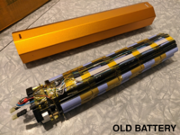
I took a few photos for my own reference, but there already exists a great documentation of a teardown
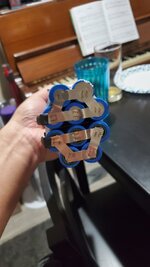
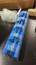
here. The two black caps come off each end with some patient and gentle persuasion with a flat end screwdriver or two. Once the caps are removed, you can push on one end, and it innards some out in one piece. It must be reassembled in the same orientation, so I would recommend taking lots of photos as you go along. Pretty much everything went smoothly. Connecting these two main battery power connectors that you mentioned to the BMS was the only part of the process that I was not 100% happy with. There are two large flat metal tabs that come from the original battery and connect to the BMS as seen
here. The tabs have a hole drilled near the end of each, and a screw fastens each of these tabs to a post on the BMS.
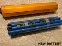
The new battery has these same tabs, but they do not have holes drilled in them. My original thought was to simply drill holes in the tabs and attach them in the same fashion. When I actually got the battery in hand, I discovered that these tabs were about 1/2" shorter than they are on the original battery. They are not long enough to reach the posts on the BMS. What I ended up doing was to cut the tabs off of the old battery and solder them, face to face to the tabs on the new battery. This extended the length of the new tabs long enough to reach the posts, and the holes were already drilled. Ideally, this should have been done with a spot welder, but I paid special care to make sure that the connection was good and solid. I roughed up each connecting surface, and used an adequate quantity of flux. I also added enough shrink wrap to match how these tabs look in the original photo above.

 www.aliexpress.com