You are using an out of date browser. It may not display this or other websites correctly.
You should upgrade or use an alternative browser.
You should upgrade or use an alternative browser.
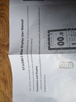
Updating voilamart with KT controller
- Thread starter Pw2000
- Start date


harryS
Well-Known Member
I would say you have a wiring problem. It's an LCD8H and a KT controller. The LCD powers up, right?
The Voilamart throttles usually include a power button and are 5 or 6 wires, while KT controllers use a three wire throttle. Maybe your conversion here used the wrong wires.
Put your LCD into walk mode to see if the motor spins. This will tell you if the motor wiring is correct.
The Voilamart throttles usually include a power button and are 5 or 6 wires, while KT controllers use a three wire throttle. Maybe your conversion here used the wrong wires.
Put your LCD into walk mode to see if the motor spins. This will tell you if the motor wiring is correct.
Hi Harry voilamart uses 3 wires for throttle but there different colours to the KT.
What I am going to do is experiment moving the wires by attaching the wires on the throttle in different combinations to the controller until it works. Like wise I am going to do this with the hall sensor plug. I think those are the only two plugs that are different. I have not tried the walk mode yet. I will try that one as well. Thanks
What I am going to do is experiment moving the wires by attaching the wires on the throttle in different combinations to the controller until it works. Like wise I am going to do this with the hall sensor plug. I think those are the only two plugs that are different. I have not tried the walk mode yet. I will try that one as well. Thanks
Hello I tried attaching controller and new LCD but the LCD does not communicate with the controller. Any ideas how I would make my controller and LCD compatible? Or which LCD would be compatible with my controller thanks for your help
Attachments


Hello Harry, I have been plugging the display into a different connector and had made an adapter specially for it because I thought the connector was wrong. I will try plugging the display into the connector you mentioned tonight and see what happens.
Thanks for your help
from Paul
Thanks for your help
from Paul
Hi Harry I tried taking the hall sensor and the throttle off and I tried all the different wire combinations on the motor and when I pressed walk on the Lcd8 the wheel would not spi on any of the wire connections. I tried plugging the old LCD s830 into the new controller and that read error 10. On the Lcd8 it does not say anything but appears not to communicate with the LCD8. I think that Means LCD us not communicating with controller. I wonder if the controller is broken.it's a new controller. Any more ideas thanks from PaulThe KT controller and LCD8H are compatible. The wire colors on the display connector should match exactly. In your picture, you have the jumper plug in the display connector. I assume you took that out and plugged the display in its place?
Here's a video of itThe KT controller and LCD8H are compatible. The wire colors on the display connector should match exactly. In your picture, you have the jumper plug in the display connector. I assume you took that out and plugged the display in its place?
https://streamable.com/dyr8f7
harryS
Well-Known Member
To verify that the controller works, check the red/black wires on the throttle connector with a voltmeter, after you start the LCD8H. They should read 4.5V. You should get 5 volts if you check the brake connectors, red to black. You should get 5 volts if you check the PAS connector, brown to black.
What are your motor connections looking like?
Three thicker wires: yellow-yellow, blue-blue, green-green?
Six thinner wires: yellow-yellow, green-green, blue-blue, red-red, black-black, and leave the white one alone?
Brakes should not be connected til you get the motor spinning.
What are the colors on the Voilamart Throttle wire?
Hi Harry I am a bit confused as to which is the throttle.
Appreciate your help
Paul
The engine is wired up yellow to yellow. Blue to blue green to green
Possible throttle 1 voilamart black to yellow KT. White to black red to brown.
Possible throttle 2 voilamart red to red KT black to black green to blue
I cannot get the wheel to move in walk mode even.
 Possible throttle
 Possible throttle
Engine wires up

Settings Lcd8
What happens when I put bike into walk mode.

Appreciate your help
Paul
The engine is wired up yellow to yellow. Blue to blue green to green
Possible throttle 1 voilamart black to yellow KT. White to black red to brown.
Possible throttle 2 voilamart red to red KT black to black green to blue
I cannot get the wheel to move in walk mode even.
Watch Not sure what these connectors do red to red black to black green to blue voilamart is the first one not sure if this is throttle | Streamable
Watch "Not sure what these connectors do red to red black to black green to blue voilamart is the first one not sure if this is throttle" on Streamable.
streamable.com
Watch Voilamart to KT controller Black to yellow white to black red to brown voilamart the first one. Not sure if this is throttle | Streamable
Watch "Voilamart to KT controller Black to yellow white to black red to brown voilamart the first one. Not sure if this is throttle " on Streamable.
streamable.com
Engine wires up
Watch Voilamart Engine wires connected to KT controller blue to blue, green to green, yellow to yellow | Streamable
Watch "Voilamart Engine wires connected to KT controller blue to blue, green to green, yellow to yellow " on Streamable.
streamable.com
Settings Lcd8
Watch Voilamart Engine wires connected to KT controller blue to blue, green to green, yellow to yellow | Streamable
Watch "Voilamart Engine wires connected to KT controller blue to blue, green to green, yellow to yellow " on Streamable.
streamable.com
What happens when I put bike into walk mode.
Watch What happens when I try to get it to work | Streamable
Watch "What happens when I try to get it to work " on Streamable.
streamable.com
I am not sure how to check the voltage to see if controller is workingTo verify that the controller works, check the red/black wires on the throttle connector with a voltmeter, after you start the LCD8H. They should read 4.5V. You should get 5 volts if you check the brake connectors, red to black. You should get 5 volts if you check the PAS connector, brown to black.
What are your motor connections looking like?
Three thicker wires: yellow-yellow, blue-blue, green-green?
Six thinner wires: yellow-yellow, green-green, blue-blue, red-red, black-black, and leave the white one alone?
Brakes should not be connected til you get the motor spinning.
What are the colors on the Voilamart Throttle wire?
These are the settingsTo verify that the controller works, check the red/black wires on the throttle connector with a voltmeter, after you start the LCD8H. They should read 4.5V. You should get 5 volts if you check the brake connectors, red to black. You should get 5 volts if you check the PAS connector, brown to black.
What are your motor connections looking like?
Three thicker wires: yellow-yellow, blue-blue, green-green?
Six thinner wires: yellow-yellow, green-green, blue-blue, red-red, black-black, and leave the white one alone?
Brakes should not be connected til you get the motor spinning.
What are the colors on the Voilamart Throttle wire?

Watch Kt controller settings | Streamable
Watch "Kt controller settings" on Streamable.
streamable.com
harryS
Well-Known Member
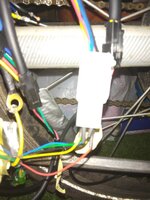
This is the Hall Sensor connector, a 2x3 plug. There will be five or six wires coming out of the motor that connect to it, matched by color. Looks like you have nothing going to it. Bike won't work unless it does. If you were to blip a properly connected throttle, with the Hall connector open like that, you would get an Error message about bad Hall sensor on a KT LCD display.

This is the throttle connector. If you had looked at your KT doc's, it would tell you it's the three pin plug with red. black, blue. The colors look right here, providing that the other end goes to your bike's throttle?

The KT doc's say Brown, Yellow, Black wires is the PAS. I cannot see the wire colors on your second video. Forget about connecting the PAS until you get the motor running via throttle or Walk mode. Also do not connect the brakes until you get the motor running. If the brakes are on, they will inhibit the motor.
It's all about wires and voltages for now. Forget the LCD settings.
A KT controller will run w/o the display. You put the jumper plug in place of the display plug, and if the throttle wiring and motor wiring is correct, applying throttle will run the motor. You can go that scenario later, if connecting the hall connector and the throttle do not get you going.
You do have a voltmeter?
This is the throttle connector. If you had looked at your KT doc's, it would tell you it's the three pin plug with red. black, blue. The colors look right here, providing that the other end goes to your bike's throttle?
The KT doc's say Brown, Yellow, Black wires is the PAS. I cannot see the wire colors on your second video. Forget about connecting the PAS until you get the motor running via throttle or Walk mode. Also do not connect the brakes until you get the motor running. If the brakes are on, they will inhibit the motor.
It's all about wires and voltages for now. Forget the LCD settings.
A KT controller will run w/o the display. You put the jumper plug in place of the display plug, and if the throttle wiring and motor wiring is correct, applying throttle will run the motor. You can go that scenario later, if connecting the hall connector and the throttle do not get you going.
You do have a voltmeter?
Hi Harry I don't have a volt meter but I saw one the other day in b and q. It was not expensive so I might get it. I'm not sure how to work it though.This is the Hall Sensor connector, a 2x3 plug. There will be five or six wires coming out of the motor that connect to it, matched by color. Looks like you have nothing going to it. Bike won't work unless it does. If you were to blip a properly connected throttle, with the Hall connector open like that, you would get an Error message about bad Hall sensor on a KT LCD display.
View attachment 95787
This is the throttle connector. If you had looked at your KT doc's, it would tell you it's the three pin plug with red. black, blue. The colors look right here, providing that the other end goes to your bike's throttle?
View attachment 95785
The KT doc's say Brown, Yellow, Black wires is the PAS. I cannot see the wire colors on your second video. Forget about connecting the PAS until you get the motor running via throttle or Walk mode. Also do not connect the brakes until you get the motor running. If the brakes are on, they will inhibit the motor.
It's all about wires and voltages for now. Forget the LCD settings.
A KT controller will run w/o the display. You put the jumper plug in place of the display plug, and if the throttle wiring and motor wiring is correct, applying throttle will run the motor. You can go that scenario later, if connecting the hall connector and the throttle do not get you going.
You do have a voltmeter?
The engine colours for the 3 thick wires are the same colour on the voilamart as the KT controller.
The hall sensor wires are the same colours on the voilamart as the KT controller. With it being a mismatched KT controller with voilamart it could be alot of different colour combinations as just because they are same colour might not mean they attach to one another. Would I have to get the 3 motor wires correct with the hall sensor wires at the same time?
I tried it with the hall sensor connected and still no power.
Here is a photo of the hall sensor.
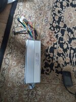
The actual controller is here
Thanks for all your help
Paul
Attachments
Harry I forgot to mention I have not tried all the 3 wire thick motor combinations with the hall sensor plugged in. If it might work a li5le bit with incorrect hallsensor connections I will give that a try. Do you think I should try that? ThanksThis is the Hall Sensor connector, a 2x3 plug. There will be five or six wires coming out of the motor that connect to it, matched by color. Looks like you have nothing going to it. Bike won't work unless it does. If you were to blip a properly connected throttle, with the Hall connector open like that, you would get an Error message about bad Hall sensor on a KT LCD display.
View attachment 95787
This is the throttle connector. If you had looked at your KT doc's, it would tell you it's the three pin plug with red. black, blue. The colors look right here, providing that the other end goes to your bike's throttle?
View attachment 95785
The KT doc's say Brown, Yellow, Black wires is the PAS. I cannot see the wire colors on your second video. Forget about connecting the PAS until you get the motor running via throttle or Walk mode. Also do not connect the brakes until you get the motor running. If the brakes are on, they will inhibit the motor.
It's all about wires and voltages for now. Forget the LCD settings.
A KT controller will run w/o the display. You put the jumper plug in place of the display plug, and if the throttle wiring and motor wiring is correct, applying throttle will run the motor. You can go that scenario later, if connecting the hall connector and the throttle do not get you going.
You do have a voltmeter?
harryS
Well-Known Member
I have hooked up KT controllers to a few different brands of motors, and they always worked when I matched the colors of the three thick wires, which were bullet connectors, and the five or six small wires in the Hall connector. Other people, with more experience, think I'm just foolish to say that, but it's true. Go back to the all colors match scenario on all 8 wires. Make sure the brakes are not connected.
There is a procedure for sorting out the wires, but you need to know the controller is powering up first.
Since the LCD is a match for the KT controller, and it powers up, it should be ready.
If you had a typical volt meter, you would set the dial to the 20V DC scale, and touch the red/black probes to the red./black pins on the throttle connector. It would show about 4.5V if the controller powers up.
Evening Harry I will get a volt meter tomorrow from a local hardware store. I have seen them somewhere.I have hooked up KT controllers to a few different brands of motors, and they always worked when I matched the colors of the three thick wires, which were bullet connectors, and the five or six small wires in the Hall connector. Other people, with more experience, think I'm just foolish to say that, but it's true. Go back to the all colors match scenario on all 8 wires. Make sure the brakes are not connected.
There is a procedure for sorting out the wires, but you need to know the controller is powering up first.
Since the LCD is a match for the KT controller, and it powers up, it should be ready.
If you had a typical volt meter, you would set the dial to the 20V DC scale, and touch the red/black probes to the red./black pins on the throttle connector. It would show about 4.5V if the controller powers up.
I have matched all the colours up on all the connections and still no power.
Will be interesting to see tomorrow what the volt meter says.
I got an intuition the controller does not work but I will find out what the voltage meter readings are tomorrow. I could be wrong as I don't know what I am doing.
Thanks again for all your advice.
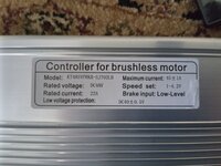
This is my battery45A controller???
What kind of battery do you have?
Will it work with my controller?
Thanks
Paul
I had a voilamart 1500w controller. The battery seems to work ok with the voilamart controller.I don't think Voilamart sells battery. (?)
The reason I got the KT controller was it said it was 1500w.
And I wanted brake regeneration but the KT controller does not work. Which is disappointing
Is this because the amps are to high on the controller?
Thanks
Similar threads
- Replies
- 3
- Views
- 690
- Replies
- 15
- Views
- 2K
- Replies
- 11
- Views
- 2K
- Replies
- 62
- Views
- 3K