Troubleshooting PAS System

AdrianDK

New Member
Hello fellow bike fanatics.

lets cut to the chase.
I have problem with my mother in law's older ebike (2010 ish), she brought it to me because her pas system stoped working suddenly.
So I checked the bike over, witch gave me this to work with.

24v Battery - holds a charge, and when connected to the bike powers the bike just fine.

motor - the display/pas controller has a "walk" funktion witch spins the motor to ish 6km/h with me on the bike from a stand still.

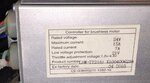
esc controller - seems fine, no lose connections or bare wires.

PAS sensor - replaced the sensor, esc supplies 4,8V to the sensor, every time a magnet hits the sensor it goes from 0V to 0,06V on the signal wire.

Its a 5 magnet disk system. I originally thought it was the PAS sensor, but now I dont know what could be wrong or even if the replacement PAS sensor was faulty from the start.

I really hope you guys have some suggestions. :)
 
It would help a bit if we knew what ebike you have, Adrian. It is entirely possible that it is the controller not reading the signal. Another strong possibility is the switch for the PAS/TAG; if it's that kind of setup; those are notorious for breaking.
 
Most PAS problems start with too much clearance between the disc and the sensor. Either that or the disc is slipping on the inside diameter. Set the clearance as tight as you can without it touching.
 
Hello fellow bike fanatics.

PAS sensor - replaced the sensor, esc supplies 4,8V to the sensor, every time a magnet hits the sensor it goes from 0V to 0,06V on the signal wire.

Hi Adrian. Typing error? Every pedal assist sensor that I've installed on my bikes was power, ground, and signal. Power is 4.3 Volts. Signal switches from 4.3 to 0.6 volts when sensor activates.

In addition, a PAS is more complex than a simple on/off speed sensor . It has to know the direction that the crank spins or it would work backwards, when the users position their pedals to mount the bike. The up/down signal we see on our voltmeters would be an non-symmetric waveform if we used a scope to watch it.

Spin it backwards. Does the motor start? Then flipping the magnet disk could be all you need to do. Depends on your sensor, which what it was mounted, etc.

Best way is to test the sensor/magnet position before you mount the pair, if you're not sure how they fit. I spin the magnet disk slowly on a rod and hold it next to the sensor. When he motor works, then I know how the two should be positioned on my bike.

You could also test the old one. If it behaves properly on a test stand, that's pointing to the controller (ESC?) fault.
 
thanks for the reply guys.
Can't say much about the brand other than I think its just a generic Chinese one.
I have already tried rotating sensor and rotating the disk while spinning the bottom bracket forward and backwards with out any luck.

ops Harry your right that was a typing error, the esc/controller (sorry its from my rc hobby days) supplies 4,8V to the sensor (red and black wires). The signal (green wire) reads from 0V to 0,016v according to magnets position. The green wire runs from the sensor to the pas controller on the handelbars.

Sadly I can't try the old sensor because the connector ripped off in removal process (will try to fix it if possible).

I have placed the system on the non drive side (I simply couldn't get the drive side pedal off) I have rotated the sensor and disk accordantly. The distance between the sensor and the disk is about 0,5mm.
 

Attachments

  • IMG_7904.jpg
    IMG_7904.jpg
    668.6 KB · Views: 4,895
Last edited:
Is there an instrument panel? They are usually the way to programming the controller. I'm guessing the old controller is shot. 7 years is a long time for a cheap Chinese bike.
 
Is there an instrument panel?
Its one of those simple ones with 3 buttons boost pas, lower pas and wall funktion. All the buttons and led indicaters seems to work though.
is there a way for me to test the panel before I go out and replace it?
 
Yes I know its not normal but its consistent, I have the multimeter connected to ground and signal, every time a magnet passes the sensor the voltage spikes to 0,016V then drops to 0V again.
As mentioned earlier I'm not even sure that the replacement sensor was working from the get go.
 
Something is wrong if you really see 0.016V or 16 mV. Whatever reads the sensor cannot be expected to read a signal swing that small. Even 1.6 volts, if that's what you meant is borderline and depends on the circuit used to read the sensor. If it was old fashioned 5 volt logic, I recall you need 2 volts, though it's been 18 years since I worked with digital.
 
Back