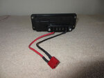
I'm in a situation where I live in a apartment style building with a secure place in our underground garage to park my XP but no power available to charge it. Folding the bike every time (multiple per week) to remove the battery for charging is not going to hack it. I'm making plans to relocate the battery to a slide-in box (home made) mounted on the rear rack.
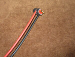
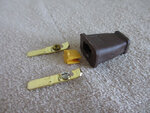
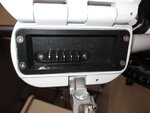
First option is I can remove the OEM male battery connector that is mounted inside the frame and extend it out to the rack. Second option is to splice into the wiring behind the OEM male connector either by direct soldered connect or via "Y" splitter and extend out to a new male connector. Third is to make a extension cord that has the same male/female connectors that the bike/battery use leaving the OEM male connector in place in the frame. I'm leaning towards the second option because with this I could still easily use the internal frame location if I felt the need to without having to change/remove anything.
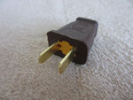
Option 1 uses the OEM male connector so just the wiring is all I need, the other two require finding the connectors. I have spent a bit of time searching for these connectors our batteries have and have come up dry. I do see some of the Belicore batteries on aliexpress come with the male connector, but I can't find anyplace that just sells the connector. I can probably kludge up my own male connector but I would much rather buy one.
So, if any of you out there find a source for these connectors, or at least the male connector (bike wiring side) please post it.
tnx
George
First option is I can remove the OEM male battery connector that is mounted inside the frame and extend it out to the rack. Second option is to splice into the wiring behind the OEM male connector either by direct soldered connect or via "Y" splitter and extend out to a new male connector. Third is to make a extension cord that has the same male/female connectors that the bike/battery use leaving the OEM male connector in place in the frame. I'm leaning towards the second option because with this I could still easily use the internal frame location if I felt the need to without having to change/remove anything.
Option 1 uses the OEM male connector so just the wiring is all I need, the other two require finding the connectors. I have spent a bit of time searching for these connectors our batteries have and have come up dry. I do see some of the Belicore batteries on aliexpress come with the male connector, but I can't find anyplace that just sells the connector. I can probably kludge up my own male connector but I would much rather buy one.
So, if any of you out there find a source for these connectors, or at least the male connector (bike wiring side) please post it.
tnx
George


")