Relocating Battery to Rear Rack

GeorgeXP

New Member
I'm in a situation where I live in a apartment style building with a secure place in our underground garage to park my XP but no power available to charge it. Folding the bike every time (multiple per week) to remove the battery for charging is not going to hack it. I'm making plans to relocate the battery to a slide-in box (home made) mounted on the rear rack.

First option is I can remove the OEM male battery connector that is mounted inside the frame and extend it out to the rack. Second option is to splice into the wiring behind the OEM male connector either by direct soldered connect or via "Y" splitter and extend out to a new male connector. Third is to make a extension cord that has the same male/female connectors that the bike/battery use leaving the OEM male connector in place in the frame. I'm leaning towards the second option because with this I could still easily use the internal frame location if I felt the need to without having to change/remove anything.

Option 1 uses the OEM male connector so just the wiring is all I need, the other two require finding the connectors. I have spent a bit of time searching for these connectors our batteries have and have come up dry. I do see some of the Belicore batteries on aliexpress come with the male connector, but I can't find anyplace that just sells the connector. I can probably kludge up my own male connector but I would much rather buy one.

So, if any of you out there find a source for these connectors, or at least the male connector (bike wiring side) please post it.

tnx
George
 
Many bike manufacturers use proprietary or difficult to find connectors. Perhaps if you post a picture, someone can ID it for you.

I assume you've checked the obvious sources:


BTW: Welcome to the Forum! You've come to the right place to ask e-bike related questions.
 
Many bike manufacturers use proprietary or difficult to find connectors. Perhaps if you post a picture, someone can ID it for you.
I assume you've checked the obvious sources:

Yup, I have looked at most of the sites you recommended. I did not see the https://www.ebikes.ca/shop/electric-bicycle-parts/connectors/con-dt-5pin.html site which shows a 5 pin Blade connector that looks simular to the one in the XP, but without any dimensional information the only way to know for sure will be to order one and see what I get. It looks like the blades are longer then the OEM but that can be dealt with, so this is a possibility.

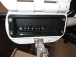
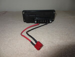
I have attached a photo of the Lectric XP frame side of the battery connector as you suggested.

tnx for your help
George
 

Attachments

  • Frame Battery Connector.jpg
    Frame Battery Connector.jpg
    128.7 KB · Views: 838
Interesting. My Pedego batteries use the 4 prong version of that same connector type. This is the female battery side:

43115

I also have had no luck finding a suitable connector. If you come across one, let me know.

I've been using simple crimp-on spade connectors for my battery projects:

43116

I build up the face of the male connector with solder and open the jaws of the female to accept the thicker lugs on the battery box.

Not a great solution since each connection has to be made separately and the correct polarity observed.
 
I'm in a situation where I live in a apartment style building with a secure place in our underground garage to park my XP but no power available to charge it. Folding the bike every time (multiple per week) to remove the battery for charging is not going to hack it. I'm making plans to relocate the battery to a slide-in box (home made) mounted on the rear rack.

First option is I can remove the OEM male battery connector that is mounted inside the frame and extend it out to the rack. Second option is to splice into the wiring behind the OEM male connector either by direct soldered connect or via "Y" splitter and extend out to a new male connector. Third is to make a extension cord that has the same male/female connectors that the bike/battery use leaving the OEM male connector in place in the frame. I'm leaning towards the second option because with this I could still easily use the internal frame location if I felt the need to without having to change/remove anything.

Option 1 uses the OEM male connector so just the wiring is all I need, the other two require finding the connectors. I have spent a bit of time searching for these connectors our batteries have and have come up dry. I do see some of the Belicore batteries on aliexpress come with the male connector, but I can't find anyplace that just sells the connector. I can probably kludge up my own male connector but I would much rather buy one.

So, if any of you out there find a source for these connectors, or at least the male connector (bike wiring side) please post it.

tnx
George
Have you tried Luna cycles or Grin technologies?
 
I've been using simple crimp-on spade connectors for my battery projects:
Not a great solution since each connection has to be made separately and the correct polarity observed.

When Plan-A was not available you went on to Plan-B... Well Done. There has been a few times it felt like I had went through Plans A-Z and was starting on Plan-AA before I figured something out. :)

If the 5-pin I found above was the correct size for you, cutting off the 5th pin (or pulling it out) might be a possibility. If you only use 2 pins for your power, say #1 & #4, cut the #3 male blade off and fit a piece of plastic in the female #3 slot. Now the connector will fit only one was and no polarity issues.

George
 
George, I like the spade lug option, on a Y-cable to the bike connector. This allows you to put the battery in the bike and use it normally (insulating the spade ends of the Y-cable, of course) or use it mounted on the rear rack.

Another possibility with that option is to carry a SPARE battery on the rear rack, in parallel with the main battery (although this doesn't solve your charging issue), essentially giving you twice the range. During my tests of the battery voltages it appeared that the three middle pins aren't connected to anything. They certainly aren't during charging; perhaps they are temperature sensors of similar for the bike...?)

I've built a carrier for my spare battery, originally intended to simply have it with me on long rides in the event I run the primary battery down, but after reading your post I think I'll cobble up the Y-cable and be able to actually run the bike from it. With the battery containing it's own on-off switch it'd allow you to select either the main, spare, or both.

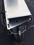
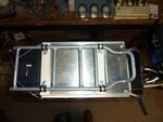
I put a hole on the bottom plate, which is .100" aluminum to allow the battery to be locked into the carrier. The top is .032" 2024-T3 aircraft aluminum, but if I were to do it again I'd use .025" - the .32 was too hard to bend with my el cheapo Harbor Freight metal brake! I flush-riveted the top to the bottom so there'd be no protrusions on the bottom surface of the carrier, but it could be bolted together with 4-40 hardware.

439584395943960

The carrier is zip-tied to the rear rack - until I can come up with a more permanent mounting arrangement. Now a 2-conductor 10- or 12-ga. cable with spade lugs connected into the bike's battery connector will allow me to use the spare battery without having to swap it with the main...

Bud
 
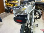
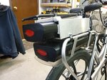
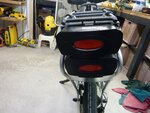
I did something similar with an aluminum battery box attached to my rear rack:

43963 43964 43965

I cut up an old rear rack and mounted it to the top of the box so I could use my trunk bag:

43966

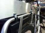
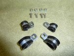
I used these insulated cable clamps to attach it to the bike. They are easily removable and don't mar the finish:

43962 43961

Rather than alter the bike wiring harness, I just swap batteries when necessary.
 
George, I like the spade lug option, on a Y-cable to the bike connector. This allows you to put the battery in the bike and use it normally (insulating the spade ends of the Y-cable, of course) or use it mounted on the rear rack.
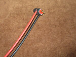
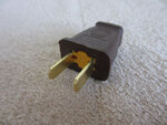
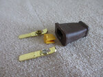
The male battery connector in the frame has a female Dean's connector on it that mates to a male Dean's on the controller. I decided to keep the setup as OEM as I could so I soldered two Dean's back-to-back to make a inline splice with 12awg silicone wire that is super flexible soldered to the joint. I ran the wire out the same hole as all the other controller wires to the rear rack. This way I'll be able to use the rack mount daily, but if I need to secure the battery I can still mount it inside. I'm going to terminate the battery wires in 30 amp Anderson PowerPole connectors. These PowerPoles will mate with PowerPoles inside my battery box that will be connected to the DIY male battery connector I'm going to cast out of epoxy (J-B Weld) using the larger of the two blades from the polarized AC connectors and include a in-line fuse holder. My reason for using the PowerPoles vs directly to the DIY battery connector is so I can do all the soldering "Off Bike".

I used these insulated cable clamps to attach it to the bike. They are easily removable and don't mar the finish:
Yup, that's what I was planning to use as well. I my case I'm going to have to make my box out of wood and the top will be removable to drop in the battery. The connector will be hard mounted to the box and the battery will be a snug fit.

I'm currently drawing it all out using a CAD program and have found a few things I would have missed with out it. Like my father-in-law used to tell me, "If you want a quality fit, Measure it with a Micrometer, Mark it with Chalk, Cut it with a Ax". :)

George
 

Attachments

  • Battery_1.jpg
    Battery_1.jpg
    106.5 KB · Views: 1,487
  • Battery_2.jpg
    Battery_2.jpg
    162.9 KB · Views: 552
  • Battery_3.jpg
    Battery_3.jpg
    97.5 KB · Views: 582
  • Battery_4.jpg
    Battery_4.jpg
    130.4 KB · Views: 562
George, use caution using JB-weld - being a metal-filled epoxy it's likely to be conductive! While it may not present a dead short, any leakage at all will cause current flow - and thus heat - across your casting. And as I recall, JB-weld is super-strong, but doesn't do well with heat... For this application, I think I'd go with polyester resin or clear epoxy - a whole lot of strength isn't necessary here, but good insulation is!

I haven't opened up the male bike connector yet - glad to hear there's a Dean's back there... I've got a drawer-full of those, so making the Y-tap will be easy. Only concern is that the end of the cable to connect to the outboard battery will be hot when the main battery is switched on, so will need to cobble up a cap to keep it from shorting if any metal contacts the male prongs when not actually connected to the spare battery.

Great idea using the prongs off a 120vac plug - thanks for the tip!

Bud
 
George, use caution using JB-weld - being a metal-filled epoxy it's likely to be conductive!
I did check their web sight and I thought I read that it was non-conductive but I will check that again. In the past I have used regular clear (yellowish?) epoxy for making connectors but never did like the look. I have some J-B Weld on hand and thought I'd use it this time because I want to drill some mounting holes in the connector thinking maybe it would be better to use. I am going to make a first connector as a test using the 30 minute stuff anyhow so if it turns out fine maybe I'll just stick with it. I will check it for conductivity whatever I use.
Great idea using the prongs off a 120vac plug - thanks for the tip!
The OEM blades are 0.059" and these are 0.060" so close enough. I used the larger polarized blade just to have a little more surface contact.

Tnx for the heads-up on the J-B-Weld, I will check on that.

George
 
I'm trying to figure out a method for securing the home-made plug to the outboard battery. In the bike the connectors are solidly secured by the bike frame, but on the outboard battery there's nothing to keep the plug from vibrating loose with potentially disastrous results, given the bare pins potentially carrying the full main battery voltage (assuming both batteries are being operated in parallel). If running only the single, outboard battery it'd be no issue - except the bike would go dead until you plugged it back in - likewise if both batteries were on board but the main was key-switched off.

Actually, that makes more sense, I guess. You'd still have the energy of both batteries, requiring only turning one off and the other on to get the same power as both being operated in parallel.

Or maybe not... running two batteries in parallel would split the load between both, perhaps yielding a slightly higher amp-hour output due to the lower current drain from each than running each battery sequentially. IIRC the capacity of a battery varies depending on the rate it's discharged...so running the two in parallel might yield more total miles than running each sequentially.

This'd be a bugger to test - not particularly difficult, but very time-consuming! What do you think? I wonder if the difference would make it worth testing this theory...? In any case, such a test is gonna have to wait for warmer weather!

Cheers!

Bud
 
n the bike the connectors are solidly secured by the bike frame, but on the outboard battery there's nothing to keep the plug from vibrating loose

Initially I was pondering this also when Plan-A was to hang it in a bag off the rear rack. As I am planning to make my own connector I figured I'd just bend a piece of spring clip metal in a |__| (rotate this 90 degrees) shape with the top edges bent in at 90 degrees to form a clip that when inserted from the rear of the male connector it would snap over the raised shoulders of the black plastic above and below the connector holding it in place. I also was intending to put a thick rubber band (cut of a innertube?) around the female portion to prevent the male connector from slipping down due to vibration.

Actually, that makes more sense, I guess. You'd still have the energy of both batteries, requiring only turning one off and the other on to get the same power as both being operated in parallel.

I think if I was planning on two batteries I would prefer to not run them in parallel, I would key one battery ON and turn it OFF when it pooped out, then key on the other one. My reason is that I'm not sure how the BMS deals with batteries in parallel (or even if this is a issue) but it's more that I simply want to keep the batteries separate so if one batttery did develope a problem it would not effect the other.

Or maybe not... running two batteries in parallel would split the load between both, perhaps yielding a slightly higher amp-hour output due to the lower current drain from each than running each battery sequentially. IIRC the capacity of a battery varies depending on the rate it's discharged...so running the two in parallel might yield more total miles than running each sequentially.

Interresting thought. Amps is Amps. The I'd think the parallel batteries would have a longer flatline voltage/current sweet spot but don't know about "might yield more total miles than running each sequentially.".

George
 
6zfshdb, who is the manufacturer of your seat that is in the above photo and what is the name of your seat if I may ask? That's a great looking setup on your batteries.

It's a Spiderflex split seat. I have circulation issues and can't use a horned saddle.


44047

Of the dozen or so I've tried, it's the most comfortable split seat I've used.
 
This'd be a bugger to test - not particularly difficult, but very time-consuming! What do you think?
Sorry, I forgot to answer this part.

I think it would be interesting to test this out if you had a constant current load to take out the variables. I would think that under this CC load, running the batteries in parallel or consecutively would yield the same results provided both batteries are identical. Running the test on a motor may very well show a difference depending where that voltage/current range (watts) that the motor is the most efficient and where that range is on the voltage discharge curve and how long are you on it.

On the other hand... the more I re-read what I just wrote I always keep coming back to what I said earlier... Amps is Amps.

A 5 amp CC load should discharge the battery in exactly the same time as a 5 amp motor load... Amps is Amps.

But you asked "running two batteries in parallel would split the load between both, perhaps yielding a slightly higher amp-hour output due to the lower current drain from each than running each battery sequentially. " so we're talking a Discharge Time measurement. I said "voltage/current range (watts) that the motor is the most efficient" now were talking Efficiency over the Discharge curve. So maybe the parallel/consecutive discharge times would be the same, but if the motor run time is longer in the more efficient section of the curve the net result would be more.... Distance?

It's time for a nap!

George
 
Yeah, I agree Amps is Amps, but it doesn't necessarily follow that amp-hours is amp-hours!

Most batteries are spec'd at a specific discharge rate for the published capacity. That capacity usually decreases with a higher discharge rate, right? So my idea of running two batteries simultaneously was to cut in half the discharge rate for each, POSSIBLY improving the amp-hour/watt-hour capacity of each battery. Of course this is only true if Lectric didn't engineer the XP system so that the battery capacity is at the highest for normal operation, and that reducing the current draw (by drawing from two batteries) wouldn't improve it.

Lectric calls their battery a 10.5 AH, and my brief initial tests show that to be pretty accurate with very mild riding. I suspect that it would be less if I was riding full out - PAS5 or full throttle... Given the wide voltage swings during normal riding with the single battery, I believe that with two in parallel those voltage swings wouldn't be as dramatic and thus "easier" on each battery than it would be running each of them sequentially. Even if I don't get more than 21 AH from them running in parallel, I believe I'd at least be able to maintain that capacity while riding faster/harder.

Testing with a CC load would yield the capacity at that load, but that might not reflect real riding where the load swings wildly with corresponding frequent voltage sags/recovery. I've read posts from other members commenting on this, and seeing how the voltage "recovers" following the heavier current demands makes me think perhaps the load that caused the voltage sag is below the "optimum discharge rate" for this particular battery.

Regarding the concern about how the controller might handle two batteries in parallel...amps is amps! It appears that the controller limits current draw to 20A, so it shouldn't matter what size power source is used - you won't see more than a 20A draw, and not even that towards end-of-charge. Once I saw that there were only two wires connecting the battery I knew the controller only reads battery voltage (it isn't monitoring temperature, cell balance, etc.), and is already handling parallel operation nicely, as the XP battery appears to be an 11S4P internally. Running my two in parallel is simply be providing it with an 11S8P source. And if I could get a couple 24v aircraft batteries to wire in series I could test that theory and ride all month on a single charge... Or, conversely, I could cobble up a "lightweight" battery - a single string of eleven 18650 Li-ion cells with about 2.5AH capacity for those short rides of only a few miles. But that would probably push them beyond their most efficient discharge rate, exactly the opposite of what I'm trying to do by using two XP batteries in parallel! Sheesh!

Right, time for a nap!

Bud
 
Back