tomjasz
Well-Known Member
- Region
- USA
- City
- Minnesnowta
GBK to US $14.45Get a new gasket
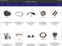
California-ebike USD $15.67 (2 left)
GBK to US $14.45Get a new gasket


I would get 1 left and 1 right... just incaseGBK to US $14.45
California-ebike USD $15.67 (2 left)

You sure you’re not Polish?I would get 1 left and 1 right... just incase

Ok GuysPossible that they just changed the male/female orientation? Note the motor end.
Take a look here.
Hint: use the desktop version of your browser on a mobile deviceBafang Ultra M620 G510 eb-bus 1T4 cable for replacement-greenbikekit.com BBS, ebike batteries, Bafang M620, Bafang M600, Bafang M500, Bafang M510, KT controller with display-GreenBikeKit.com
Bafang Ultra M620 G510 eb-bus 1T4 cable for replacement.www.greenbikekit.com
View attachment 119001View attachment 119002


Hi GRDoes the bike have 2 batteries?
If so I'd guess the black box is for battery paralleling/distribution
It's hard to tell from the pictures... But I'm pretty sure that the black box's are all battery distribution and nothing to do with CANbus.Hi GR
Yes it does, Dual batteries.
What does the other black box with the 8 metal bars do?
Can both of these black box's be Canbus also?
I also think that the main connection cable is not Canbus,
unless there is a hidden "something/item" that I haven't found yet.
I wish I could find a diagram of all the components for this bike,
it would make a lot easier.............LOL
Thanks,
Your thoughts and suggestions,
Don
Hailong? Made by ShanShan.4 bladed battery case
I wouldn't go that far for a bench test.Can someone direct me to a location, where I may find the 4 bladed battery case
power plugs, that fit the Warthog OEM batteries?
I have to make a bench testing power plug.
Tia,
Don
TomHailong? Made by ShanShan.