Making e-bike per-cell charger...

Bekjan

New Member
Hello

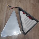
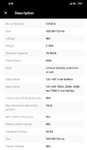
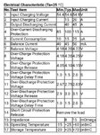
I have a diy battery ICR18650-26F 13S7P 48V 18Ah (see how it builded, tests https://www.instagram.com/explore/tags/electric_bike_apache_log/ )
I charged it with a standard 54V4A charger, but the shutdown happened ahead of time, as it turned out one parallel had charged up to 4.2V earlier than the others, the other parallels only charged up to 3.98V. This is sad, rather, either the marriage-cells or incompatible internal resistances, something else (I did not test each cell for capacity, current output and internal resistance, even 91pcs!).
While the necessary equipment is going to test the cells, I thought about the individual charging of each cell ...
It sounds crazy, but it ensures that each cell is charged up to 99%.
First of all, I looked on the Internet, maybe someone has already done this .... but did not find in the subject of electric bicycles.

Future changes in the current battery:
0) Increase the capacity to 31А - 13S12Р (156 cells 18650) 1.23$/pcs
2019-07-08_133025.jpg

1) For each cell, connect a 2P3T slide-switch (3А250В, 6А125В should be enough for 2-4A cells) 0.09$/pcs
2019-07-08_131730.jpg

2) For each cell, connect a charging / protection module based on TP4056 (5V 1A) to the switch 0.2$/pcs
2019-07-08_131750.jpg

3) For each TP4056 connect diod shotki 1N5822 to reduce charge voltage up to 4.1-4.15V for increase cycles charge/discharge 0.02$/pcs
2019-07-08_132426.jpg

3) Optionally fuse 250V2A to each cell 0.015$/pcs
2019-07-08_132034.jpg
4) Approximately 0.8m of wire for each cell-charger&diodshotki-slideswitch 0.11$/m

For power supply of charging modules, power units S-400-5 (5В80А 400W) 2pcs are ordered, this should be enough for 140-160 TP4056.

Total: 156 switches ... 156 TP4056 chargers, 156 diodes 1N5822, 156 fuses, about 120m of wire (I don't know how it all fits in the frame of the bicycle but fire in the eyes burns with a green flame :eek: )

After all the connections, I will have two charges:
1) Standard 54V4A - system plugin
2) Per-cell charger - switch system

I think on the first charge at all as well - just connect via the XT60 plug or any other convenient plug.

Per-cell charger:
1) Open the battery box
2) Disable the cable to the regular bms (just protection from the human factor)
3) Switch all 156 switches to the charging position
4) Connect the power supply of TP4056 through 2 power supply units.
5) After charging (all 156 TP4056 LEDs should be lit), toggle the switches
6) Connect cable to bms
7) Close the battery box

What do you think about this? What can be done easier? Did someone do something like that?


Sorry if the text looks strange - translate google.
 
Last edited:
I do not like your idea of individual charging. It's too much complexity and too many connections to break. You could use a charger for every bank of parallel cells, so that reduces to 13 individual circuits, but even that is unwieldy.

The purpose of a well designed BMS is to balance your battery when you get one group at 4.2 and the rest at 3.8 volts. It will drain the 4.2V group down a few tenth of a volt and then start charging again, allowing the rest to catch up. This process repeats until everything is even, and could take a day or two to finish. However, not all BMS boards have these balance circuits.

You could also put an individual light load on that 4.2V group and drop it down to 3.8. Then reconnect the charger and see if the pack now charges evenly.

If you used a mixed collectionof cells of different ages, and different Ah capacities, your battery might never work very well.
 
I do not like your idea of individual charging. It's too much complexity and too many connections to break. You could use a charger for every bank of parallel cells, so that reduces to 13 individual circuits, but even that is unwieldy.
I agree that the more difficult the more unreliable, but I want to go all the way from the beginning to the madness :D+
But yes, I can use not individual charges, but break the battery if not into parallels but into units, 2-3-4 cells per unit and charge them separately

The purpose of a well designed BMS is to balance your battery when you get one group at 4.2 and the rest at 3.8 volts. It will drain the 4.2V group down a few tenth of a volt and then start charging again, allowing the rest to catch up. This process repeats until everything is even, and could take a day or two to finish. However, not all BMS boards have these balance circuits.

You could also put an individual light load on that 4.2V group and drop it down to 3.8. Then reconnect the charger and see if the pack now charges evenly.
Unfortunately, I do not have such a smart bms on charging :confused:


If you used a mixed collectionof cells of different ages, and different Ah capacities, your battery might never work very well.


The battery was collected from "new" china-cells from one batch, I measured the voltage in all cells and it was the same everywhere 3.68V. I tested only one cell in a semi-manual mode without any smart chargers / tester. So the cell was able to give a current of 0.5A-0.43A for 5 hours and 48 minutes, which is roughly roughly 2400 mAh
 
2) For each cell, connect a charging / protection module based on TP4056 (5V 1A) to the switch 0.2$/pcs
There are several versions of this PCB. Use caution, there are several clones that are not good quality and lack protective features of the original.
 
A BMS is only about $25 USD shipped from China, if you get a good vendor. You'll spend more on tour little USB chargers.
I have bms 13s40A but it charge off if one parallel has 4.2V. Or it still charging but balancing? Just on charger the green led is off
 

Attachments

  • Screenshot_2019-07-09-08-39-11-621_com.alibaba.aliexpresshd.jpg
    Screenshot_2019-07-09-08-39-11-621_com.alibaba.aliexpresshd.jpg
    38.7 KB · Views: 294
  • Screenshot_2019-07-09-08-39-26-306_com.alibaba.aliexpresshd.jpg
    Screenshot_2019-07-09-08-39-26-306_com.alibaba.aliexpresshd.jpg
    134.6 KB · Views: 295
The purpose of a well designed BMS is to balance your battery when you get one group at 4.2 and the rest at 3.8 volts. It will drain the 4.2V group down a few tenth of a volt and then start charging again, allowing the rest to catch up. This process repeats until everything is even, and could take a day or two to finish. However, not all BMS boards have these balance circuits.

I wonder how common these in fact are...

As to the OP....
I assume from the phots that it’s an Ann Power sourced BMS. Pretty average but popular. Likely as good as a majority used in OEM bike batteries. I looked quickly and it didn’t appear to be a balancing capable BMS, but so many aren’t. I typically do occasional MONITORED long, 8hr plus, charge cycles. I’ve had packs that needed 2 cycles to balance. Just always monitor long charge cycles. BTW a lot of us like Ann Power. But I’m becoming enamored by Bluetooth BMS.
Yes, it's Ann Power bms
Thank you
 
The purpose of a well designed BMS is to balance your battery when you get one group at 4.2 and the rest at 3.8 volts. It will drain the 4.2V group down a few tenth of a volt and then start charging again, allowing the rest to catch up. This process repeats until everything is even, and could take a day or two to finish. However, not all BMS boards have these balance circuits.

You could also put an individual light load on that 4.2V group and drop it down to 3.8. Then reconnect the charger and see if the pack now charges evenly.

The last two days I was engaged in the discharge of parallels to 3.000V
Then I charged it with regular charging at 4A (3.8A in reality) and noticed that after charging the BMS started to heat up. Specifically heated resistors to 46-47 degrees Celsius.
IMG_20190713_130310.jpg

Within 4 hours, I measured the voltage of each paralell and wrote them down in a table - the voltages began to fall but not exactly level off.
2019-07-13_125924.jpg

I discharged the battery to 54.00V and the heating of the resistors stopped. The paralell voltages slightly aligned, I will try several discharge-charge cycles.
More and more I start to look in the direction of "smart" bms with bluetooth ...
 
I looked at the specs on your BMS. Yes, it has a balance capability, Look on the specs. It says the balance current is around 50ma. And it's balancing.

I think the resistors that are getting hot are your balance resistors because they are doing their job. THere should be more on the other side, for a total of 13 resistors. The "820" indicates they are 82 ohms. From Ohms law , I= V/R. Divide 4 volts by 82 ohms and you get 48 ma for the balance current. Amazing how the math works.

My suggestion is to use your BMS. Puting a bluetooth on it is fun for about 20 minutes. Then you know everything there is to know, and you might never look again.
 
today i got parcel 60 cells ICR18650-26F (EAIEP China) and tester YR1030+

i have been measured all cells for internal resistance and got that data:

15.6 mOm: 2pcs
15.7 mOm: 1pcs
15.9 mOm: 1pcs
16.0 mOm: 3pcs
16.1 mOm: 3pcs
16.2 mOm: 3pcs
16.3 mOm: 1pcs
16.5 mOm: 3pcs
16.6 mOm: 4pcs
16.7 mOm: 3pcs
16.8 mOm: 4pcs
17.0 mOm: 4pcs
17.1 mOm: 1pcs
17.2 mOm: 7pcs
17.3 mOm: 2pcs
17.4 mOm: 4pcs
17.5 mOm: 3pcs
17.6 mOm: 2pcs
17.7 mOm: 3pcs
17.9 mOm: 1pcs
18.0 mOm: 3pcs
18.4 mOm: 2pcs


is it good range of internal resistance? could be used in one battery pack?

interesting, how much resistance in used battery pack 13S7P (145km range)...
 
Please, help me choose a scheme for sorting cells by internal resistance (mOhm). I do not have data on the capacity of each cell (even if there was equipment, then it will take weeks)
http://repackr.com/ offers this option (according to the logic of sorting the capacity, I substituted the capacity of the cells instead of the capacity 😝):
36561

second option with the same resistance in one parallel:
36562


What is better for battery health?
It seems that the option from the site http://repackr.com/ is more profitable in that the best cells compensate for the worst.
The second option is worse in that the parallel with a higher resistance P13 will be discharged faster and thereby the bms will more often work.
 
It looks like in the current implementation of the battery box - there is no place for crazy per-cell charger...
at least in this project an electric bike

36910
 

Attachments

  • IMG_20190821_105250.jpg
    IMG_20190821_105250.jpg
    128.8 KB · Views: 343
Back