KT Controller/Display on a Pace 500?

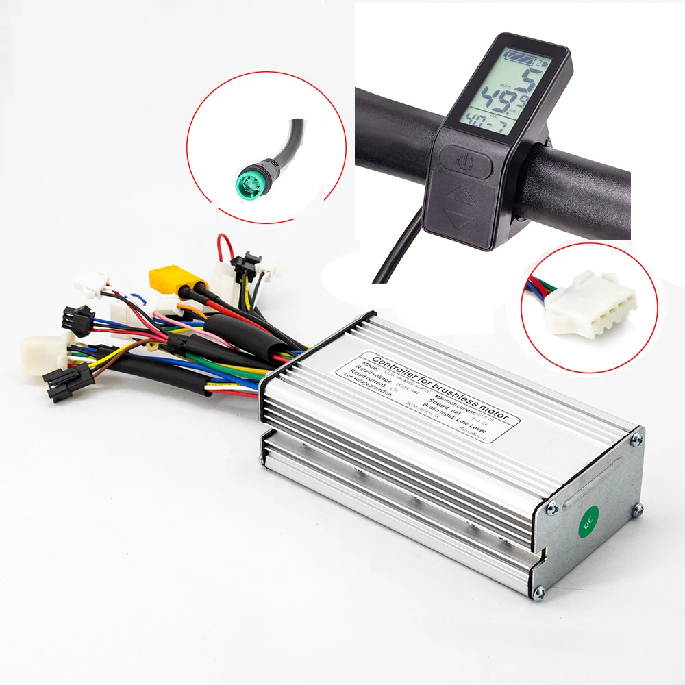
Here's the 25A model that I bought last month. The above measurements were mine, not their specs. This will replace the controller that I drowned last year.


And here's the 20A model that I bought. Ditto for the measurements. I didn't need it but like to keep a spare on hand.

 
Last edited:
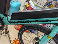
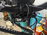
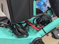
The controller I've been using recently is the KT-22a w/waterproof connectors. 1:4 cables make for a neat job. Awesome controller, 9 fet (tube) able to deliver nearly 1000w on our Espins. It is a snug fit, but with carefull packing of the wires, they do fit. Motor connector was one I have never seen, forget what they call it, so I had to make an adapter. Dimensions are 12.5*6.5*3.6 cm/4.92*2.56*1.42in

I've used the KT-17a waterproof as well. 6 fets and it's about an inch shorter. Works fine on our 500w Bafang

All were purchased on Amazon. Don't have the patience for Aliexpress, although I've ordered from PSPower on several occasions. Good people I'm not shy to endorse, but she's not carrying the KT-22a for some reason.

I was in a hurry and went with a square wave to see if I could get away with it. I can hear it, but it's nothing objectionable. If I didn't know it was a square wave controller, I probably wouldn't even have noticed it. Given the time, the sine wave might be worth searching for. -Al
 
Sorry, I didn't mean to abandon my thread, real life pulled me away for a bit.

I wasn't able to cancel my orders - they sellers got them shipped first thing Monday. So the KT controller & display will be coming my way regardless. I can still return them after they arrive in 2+ weeks, but harryS' post gives me hope. The controller that is coming is the 22A model, so hopefully the guts of it won't be too much bigger than the 20A. I should be able to work with a controller that is 26x54x88 mm. If not, I guess I'll have to look at putting on an external box or going with the Bafang controllers. Probably Bafang at that point if the return shipping isn't too expensive.

One more thing I found with the Bafang is that it has a 3 pin brake sensor and my current brakes have 2 pins. Not sure if that would be a simple rewiring job, or if I'd need new brake sensors. The brakes are hydraulic, so it would be more involved than with cable brakes I'd think.

edit -> here's the link to the controller I bought (the 22A option): https://ebay.us/SJLKQy
Hi, so does this fit in the stock Pace 500 frame, or did you remove the guts and modify in some way?

What Amp rating is the stock controller? I dont need anything larger, but also dont want to go down? Maybe its 20A?

Link to the 22a from ebay Ebay 22a

Also, any other modifications or adapters needed for any of the cabling?
 
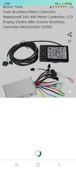
I have a Pace350 that rides fine except no speed display & E30 error. I verified the speed sensor signal is coming out of the hub motor. Aventon said it can be either display or controller. Trying to save $ was thinking of going w/ this duo, anyone tried it? The biggest issue i see is the connectors will need to be adapted, but appears much more customizable. Thx,Don
 

Attachments

  • Screenshot_20230804_165049_Amazon Shopping.jpg
    Screenshot_20230804_165049_Amazon Shopping.jpg
    95.3 KB · Views: 147
I have a Pace350 that rides fine except no speed display & E30 error. I verified the speed sensor signal is coming out of the hub motor. Aventon said it can be either display or controller. Trying to save $ was thinking of going w/ this duo, anyone tried it? The biggest issue i see is the connectors will need to be adapted, but appears much more customizable. Thx,Don
 
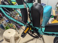
Update.... I successfully was able to utilize the generic controller & display on my Aventon. Once I got it configured it works great. I was able to lower the " ramp up speed" for pedal assist to be more gradual. The wife likes it much more, plus there's the option to have a headlight, up to 9 levels of pas, currently using 5. The controller wiring needs to be adapted since connectors are not same and it's a snug fit getting the controller to fit into the frame.
 
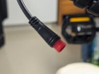
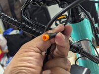
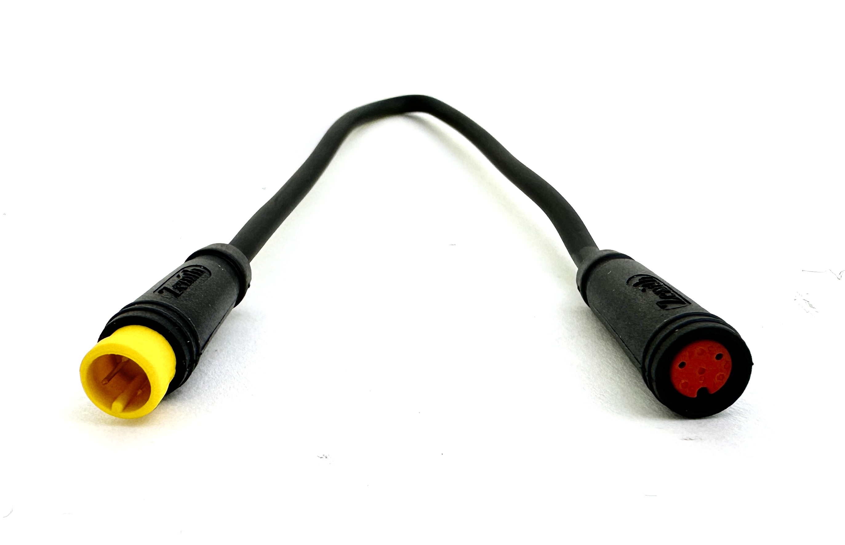
Hello All: I was able to follow this thread and get a KT 22A controller to work with the PACE 500.2 step thru bike. The last piece that I am looking to solve is the brake motor cutoff which is 3 pin Julet (yellow) from the controller harness to the 2 pin julet on the Tektro hydraulic brake (red). I measured the voltages on the 3 leads in the 3 pin julet and none of them are 5 volts. The controller brake is a low cutoff. Which of the 2 wires in the 3 pin yellow julet connector would I connect to the 2 pin julet connector? Looking for some guidance.
 

Attachments

  • PXL_20240922_005356129.jpg
    PXL_20240922_005356129.jpg
    446 KB · Views: 25
  • PXL_20240922_005359219.jpg
    PXL_20240922_005359219.jpg
    353 KB · Views: 34
  • PXL_20240922_005402347.jpg
    PXL_20240922_005402347.jpg
    377.5 KB · Views: 28
  • PXL_20240922_005410064.jpg
    PXL_20240922_005410064.jpg
    282.8 KB · Views: 28
  • PXL_20240922_005503404.jpg
    PXL_20240922_005503404.jpg
    149.5 KB · Views: 29
  • PXL_20240922_005602221.jpg
    PXL_20240922_005602221.jpg
    290.3 KB · Views: 21
  • PXL_20240922_005612724.jpg
    PXL_20240922_005612724.jpg
    349 KB · Views: 26
Which of the 2 wires in the 3 pin yellow julet connector would I connect to the 2 pin julet connector?
Strap the brake lever and probe the pins. Check all 3 combinations of pins. If the sensor is NO, then you should see a short on your ohm meter. When you see it, release the strap, you’ll see the sensor open.

If the sensor is NC, then you’ll see an open instead.

If you see the short (assuming sensor is NO) and still your motor doesn’t cut out when brake is active, you MAY have to reverse the pins.
 
@Slaphappygamer thanks! The brake lever side is the one with the 2 pin julet. I put an ohm meter across and when the lever is pressed the ohm meter reads a short. So it is an "NO".
The real issues is with the 3 pin Julet (yellow colored) in the end of the harness. I turned on the bike and used the throttle in PAS 1 and tried shorting 2 wires at a time of the 2 wires and the motor does not cut off.
With the controller on, I measured the voltage between the each of the 2 wires of the 3 pin julet and none of them have a 4.5 V to 5 V reading. All 3 combinations are in the 50 mV range. Not sure how to debug this further. I use an 4 to 1 harness for the KT controller.
 
Last edited:
I figured out the solution. I connected the 2 pin Julet of the brake lever to wires of the 3 pin julet from the harness and tried various combinations by trial and error. Finally got the 2 correct pins on the 3 pin Julet. All works well. Now onward to programming the controller.
 
As an aside for the next person who comes along and reads this: There are 2-to-3-pin adapter cables widely available as this is a fairly common issue. Typically very short extensions.


You can buy cables that are built-in to handle the red plugs. My two most recent KT controllers bought this year use 1T4 cables and those 1T4's came with red plugs. BBSHD and BBS02 wiring harnesses with red plugs are available from California Ebike.


Also, Biktrix did a tutorial on hacking 2- to 3-pin connections like was done here.


Personally I would never do the hack and instead find a plugin solution. Have always had a plugin solution. I did the first one of these for a build in 2018, so I've had plenty of opportunities to fail at finding a 'proper' adapter and never have.
 
I was able to find the right harness on AliExpress after I had done the adapter cables myself. AliExpress has a poor english search engine and it takes time to identify things using their pictures. Always end up with a bunch of useless cables in any project.
 
I had had some weird 2 pin Julet connectors on my Tektro brakes that I couldn't find anywhere,..

20230105_123659.jpg
20230105_123738.jpg


I only had about two inches of wire coming from the brake lever/switch so I didn't want to cut the connector off to solder the wires together directly.

I ended up cutting off the red 2 pin brake connectors from my 1-5 cable and soldered ½" pieces of solid core telephone wire to the stranded wire from the 1-5 cable and the telephone wire worked as pins to insert into the weird Julet brake connectors.

Then I put dielectric grease on the connection pins and covered the whole connection with shrink tube.

20230328_142112.jpg


There is 4:1 shrink tube available with glue, and it was large enough to fit over the entire connector, then shrink down small enough to snug up and seal around the much smaller wires.
 
Here are the KT LCD 8H display settings for the PACE 500.2 KT controller. Works well.

You might want to try C5=0
That gives you three level slow start to accelerate more gently without the full surge of power.

Or,.. you can set C4=4 and turn down your power in first throttle gear to 20%
That allows you to go through your throttle gears to accelerate with the power you want starting at 20% in first throttle gear up to 100% in fifth gear.

That's what I did (along with cutting my power in half).
First throttle gear worked out to be about 6 kph at very low power, and it works great for 3 point turns or going really slow on rough trails, but you still get full power (½ power in my case) in throttle gear 5.

Or you can just let the controller take care of acceleration/power using C5=0
 
AliExpress has a poor english search engine and it takes time to identify things using their pictures.

I spent dozens of hours trying to join AliExpress and trying to find what I wanted.
The pictures were usually the best way to try and figure out what you're actually getting, but even then there were issues.
I noticed that the KT controller dimensions were usually showing the dimensions of the box, but some were including the mounting tabs on the end of the box as well.


I did find out some basic information though,..
The KT controller boxes are all standard sizes. The smallest one is 15 amps and has 4 mosfets inside (I think?), then they improved the efficiency of the mosfets and the same KT controller box is now 17 amps.
The next size up went from 20 amps to 22 amps.
Now there are controllers with the same amp rating but a different number of mosfets depending on which mosfets are used.

EDIT: The number of mosfets are 6, 9, 12, and 15. Multiples of 3 for each of the three phase wires.


A dual mode controller means that it will work with both 36 volt and 48 volt batteries (and I think that they added 52 volt now too?)
My battery is 48 volt, and I ran it down once until the controller cut out, so I turned it off and back on again to try and make it home.
(I was running on fumes. 😂)
After the third reset, my display thought that I had a 36 volt battery and the battery indicator showed full charge. 😂

All hub motors are basically the same with 3 heavy gauge phase wires, 3 smaller gauge hal sensor wires with colors matching the phase wires, positive and negative +5 volts wires to power the hal sensors (usually black and red), and a speed sensor wire (usually white) which is also a hal sensor running off the same +5 volts.
Some Extremely Rare hub motors have an additional motor temperature wire.

Interestingly, the KT display is switchable to show either the ambient air temperature or the motor temperature, but there is no connection for a motor temperature wire.
If you do want to connect a motor temperature wire, you have to install the temperature sensor inside your motor, then string the wire all the way up to and inside the KT display, and solder it onto the circuit board at the appropriate place which isn't labeled or possibly isn't even on the circuit board. 😂
Switching the display to "motor temperature" might not switch it to anything at all. 😂

Any hub motor will run off square wave or sinewave. A square wave controller is more efficient, but all that extra efficiency is lost and wasted as heat and noise in the motor.
The noise itself can be hard on the motor because it vibrates and knocks at the motor which can eventually knock the glued magnets free inside the motor. It's hard on the bearings and everything inside the motor especially with the added heat that the motor has to deal with.

A sine wave controller is a lot nicer to your motor, but it isn't as efficient as square wave, so it wastes more power and gets hotter.

I personally would rather have the waste and inefficiency in the controller because it's a lot cheaper and easier to replace the controller than the hub motor.
A sine wave controller is only a few dollars more than the equivalent square wave controller.


Always end up with a bunch of useless cables in any project.

I've got lots of spare cables and connectors and almost a dozen throttles, but I don't consider them useless at all.
I consider it stocking up on supplies, so I can always make a connector/cable without having to wait for delivery.

Women like to collect shoes and purses.
I like to collect ebike parts and pieces. 😂
 
Last edited:
I was able to find the right harness on AliExpress after I had done the adapter cables myself.

It's kinda surprising that the 2 pin brake connectors aren't more commonly available.
Apparently the third pin is to activate a brake light, but I'm not aware of any e-bikes that use a 3 pin brake switch.

My new ebike has a brake light but the tektro brakes have the normal red 2 pin Julet connector.

The controller uses the single brake switch to cut out the motor and to activate the brake light.


Keep in mind that the headlight output on the 1-5 cable is battery voltage (48V in my case) but it can only put out 0.2 amps (10 Watts) or you'll fry the circuit (it's not fused)

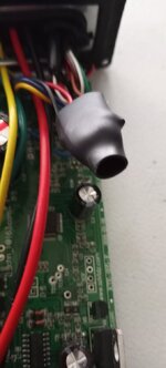
There is a separate daughter board inside a KT controller with a light output, that powers the headlight.

If you cook your headlight output, the controller still works fine, but with no headlight.

I found at the time that all the 1-5 cables were about a foot longer than the 1-4 cables.
 

Attachments

  • 20230118_141800.jpg
    20230118_141800.jpg
    85.6 KB · Views: 25
  • 20230118_141817.jpg
    20230118_141817.jpg
    156.1 KB · Views: 19
Last edited:
^^Thats the same daughterboard that fried when one of my lights shorted out. Turned out, my light fried because it was a 12v light being fed full pack voltage. I ended up desoldering that board, because it was ugly and dead. Controller worked fine without it.
 
^^Thats the same daughterboard that fried when one of my lights shorted out. Turned out, my light fried because it was a 12v light being fed full pack voltage.

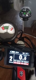
I disconnected my headlight and used the headlight output to power my 48 volt fuel gage,..

I use the headlight switch in the display to turn the ammeter on and off.

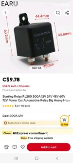
You can hook up the headlight output to a 60 volt relay to switch power directly from your battery to high power lights.
 

Attachments

  • 20230930_143400.jpg
    20230930_143400.jpg
    103.2 KB · Views: 24
A 48v relay will probably be OK, but a fully charged 48v battery is 54.6v

Screenshot_20240924-173714_AliExpress.jpg
 

Attachments

  • Screenshot_20240924-173200_AliExpress.jpg
    Screenshot_20240924-173200_AliExpress.jpg
    103.2 KB · Views: 26
Back