Hi all,
I've been building an e-Bike and recently it's all gone a bit Pete Tong, so I'm hoping this is the place where all the experts hang out!
The basic question is: Has anyone pulled apart a Voilamart 1500W rear hub kit that has the controller built into it?
And if so, please can you help me to work out the function of each of the wires in the cable that disappears into the motor casing?
I've done quite a bit of the work (so I'm not asking to be spoon-fed) but don't want to blow up the controller and screw up the entire build at the last hurdle.
This is the story so far:
The bike's based around a Scott Nitrous 10 downhill frame and battery pack that I bought from a friend, and the aforementioned Voilamart 1500W rear hub kit.

All was going well until my choice of bottom bracket and chainset determined that the original PAS sensor wasn't going to fit.
No problem I thought; just buy one of the Hollowtech style PAS sensors.
It only took about a week to come from China, but on coming to plug it in, I found that it had a male instead of female plug, which meant the main loom would need to be modified as that had one too.
Again, no problem I thought, just take apart the back of that big scary-looking plug and re-solder the 3 wires.
Then it all went pants.
The plug wouldn't "just" come apart, because it was basically stuck together and designed not to be messed-about with.
And when brute-force and ignorance finally forced it to give up, some of the connections came away from their terminals - great.
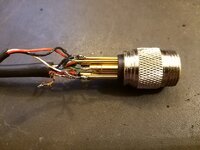
Things went from bad to worse, and now I need to replace this entire plug and socket with straight through soldered joints (because I can't find the plug and socket online).
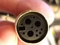
The big problem is that the wiring convention seems to be different on each side of the plug and socket.
Most of the colours are the same, but some are odd, and others seem to do different things.
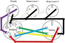
I've continuity-tested the wiring loom and drawn the following schematic:
I've also photographed where the main cable enters the motor casing and attaches to the circuit board:
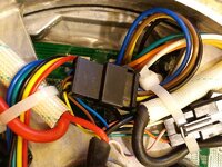
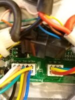
(Top LHS row of wires are white, pink, green and ORANGE - yes I know it looks like yellow!)
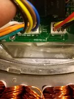
I basically need to know which of the following colours goes to pins 1 to 8 from the schematic.
This is what I think I know, but please feel free to prove me wrong:
Red (taken as a thin feed from main +ve) - ?
White (labelled SL on circuit board) - ?
Pink (labelled TA) - I know this goes to the PAS sensor.
Green (labelled TXD) - I know this goes to 2 (also green).
Orange (labelled 5v+) - I know this goes to the PAS sensor.
Black (labelled GND) - I know this goes to the PAS sensor and THINK it goes to 8 (also black)...?
Yellow (looks like it's labelled P45 but should it be RXD?) - I know this goes to 3 (also yellow).
Brown (not sure if this is labelled RXD or SP) - ?
Blue (not sure if this is labelled SP or D1) - ?
Thanks in advance to anyone who can lend any constructive criticism.
Regards,
Neil.
I've been building an e-Bike and recently it's all gone a bit Pete Tong, so I'm hoping this is the place where all the experts hang out!
The basic question is: Has anyone pulled apart a Voilamart 1500W rear hub kit that has the controller built into it?
And if so, please can you help me to work out the function of each of the wires in the cable that disappears into the motor casing?
I've done quite a bit of the work (so I'm not asking to be spoon-fed) but don't want to blow up the controller and screw up the entire build at the last hurdle.
This is the story so far:
The bike's based around a Scott Nitrous 10 downhill frame and battery pack that I bought from a friend, and the aforementioned Voilamart 1500W rear hub kit.

All was going well until my choice of bottom bracket and chainset determined that the original PAS sensor wasn't going to fit.
No problem I thought; just buy one of the Hollowtech style PAS sensors.
It only took about a week to come from China, but on coming to plug it in, I found that it had a male instead of female plug, which meant the main loom would need to be modified as that had one too.
Again, no problem I thought, just take apart the back of that big scary-looking plug and re-solder the 3 wires.
Then it all went pants.
The plug wouldn't "just" come apart, because it was basically stuck together and designed not to be messed-about with.
And when brute-force and ignorance finally forced it to give up, some of the connections came away from their terminals - great.

Things went from bad to worse, and now I need to replace this entire plug and socket with straight through soldered joints (because I can't find the plug and socket online).

The big problem is that the wiring convention seems to be different on each side of the plug and socket.
Most of the colours are the same, but some are odd, and others seem to do different things.
I've continuity-tested the wiring loom and drawn the following schematic:

I've also photographed where the main cable enters the motor casing and attaches to the circuit board:


(Top LHS row of wires are white, pink, green and ORANGE - yes I know it looks like yellow!)

I basically need to know which of the following colours goes to pins 1 to 8 from the schematic.
This is what I think I know, but please feel free to prove me wrong:
Red (taken as a thin feed from main +ve) - ?
White (labelled SL on circuit board) - ?
Pink (labelled TA) - I know this goes to the PAS sensor.
Green (labelled TXD) - I know this goes to 2 (also green).
Orange (labelled 5v+) - I know this goes to the PAS sensor.
Black (labelled GND) - I know this goes to the PAS sensor and THINK it goes to 8 (also black)...?
Yellow (looks like it's labelled P45 but should it be RXD?) - I know this goes to 3 (also yellow).
Brown (not sure if this is labelled RXD or SP) - ?
Blue (not sure if this is labelled SP or D1) - ?
Thanks in advance to anyone who can lend any constructive criticism.
Regards,
Neil.

