Hi! Greetings from beyond the Great Water! I don't speak your language fluently, so you have to guess what Google Translate means

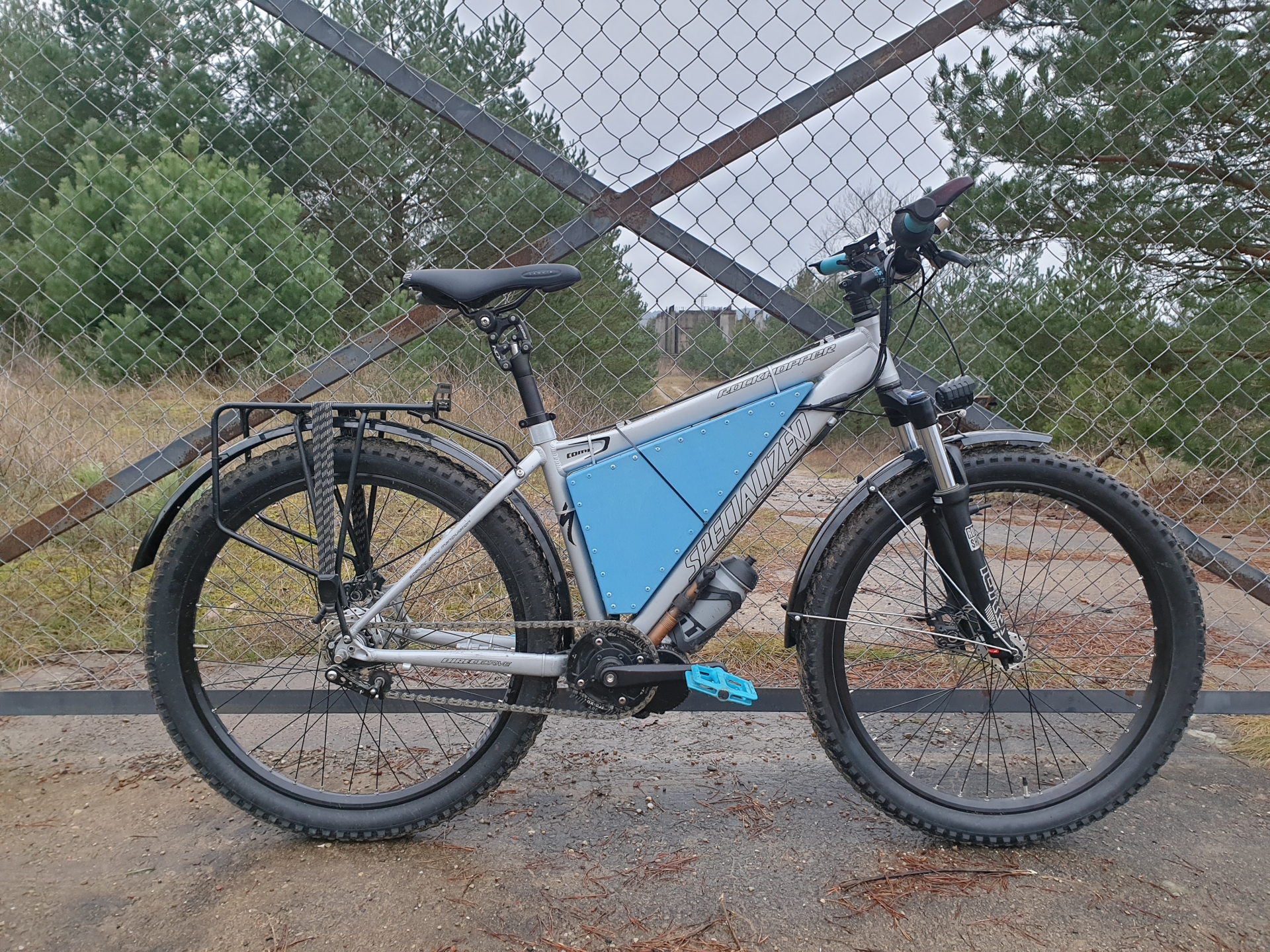
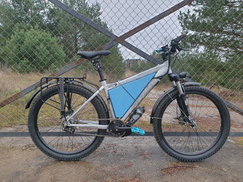
I have a Bafang BBS02B (48V, 750W) with a 48V battery (13s6p, 17.6Ah, charged 54.6V). My bike has 26 ”wheels, 2.5” tires, front sprocket 32t, rear is IGH (12t-29t). The vehicle weighs 26 kg. Together we weigh about 110 kg. What I expect from my machine is versatility and failure-free operation.
I am a tourist with an off-road flair. I also use the bike to commute to work. I like the bike, I like cranking, I like effort, I like to get tired, but sometimes I want to go further, faster, or without a drop of sweat - just get to work. When changing the settings of the controller, I expected that the engine would not crank the crank faster than I can follow, but at the same time it would be able to significantly support me when necessary - at all levels of support. That he would help me, but not do it for me. Of course, I wanted it to be as universal as possible. Such and for hills, and flat, and hard, and loose, and slow and fast - I have it all in the region where I live. I wanted jumps in boost levels to be easy, linear and logical to predict and even count in my head. I wanted the engine to be responsive, but at the same time as smooth as possible. I also wanted the BBS02B to respect the battery. And finally, I wanted to put it on a 5-point scale, because I hate unnecessary clicking. Of course, I knew it was impossible (because the BBS02B does not have a strain gauge), but I thought that it would definitely be possible to work out some sensible settings - that is, for me, far from those imposed by Bafang, but also distant from those proposed by resellers.
I think I achieved the above goals to a large extent! I can even say that I am delighted with what I have achieved! However, I must admit that there are things that I have not jumped over yet and I do not know if it is even possible in such a simple system. I do not even know if I want to, because I already have a really great ride. I must point out that these are not the perfect settings for everyone! These do not exist! I composed them only for myself, but I must admit that they seem universal to me, that I am extremely curious about the opinions of people who dare to test them at home. Dare? In fact, there is nothing to be afraid of. The only hazard is the mishandling of a throttle that can deliver 100% of the engine's potential.
I change the parameters stored in the controller via the "Speeed" application available for Android devices. I made some of the charts in the simple application "Chart Maker Pro", and in the implementation of the second part, the calculator "GeoGebra" turned out to be indispensable - Jesus, what possibilities it has! I am sorry that I am such a leg in mathematics and I can not use even half of its potential. GPX files during field tests were generated for me by "Locus Pro" - the most advanced GPS navigation application, which I will advertise always, zealously, everywhere and free of charge. Because she's a fanatical!
I do not like working in the dark, so to understand what and how individual parameters change, I decided to draw a sketch of the power (W) curve of engine support depending on different settings. I think I managed somehow. What you will see below is a picture of first of all personal feelings, few measurements and really many hours of reflection, observation and experiments in the field. BIBLE (
https://electricbike-blog.com/2015/06/26/a-hackers-guide-to-programming-the-bbs02/) and the thread on endless-sphere.com on the occasion of which it was created were for me foundation. I like to think of my work (ohoho!) As a development of the guide linked above, but I realize that for some of you, what I am breaking down into small details below is "obvious obvious". I am a novice, I have had an assisted bicycle for only a few months. I hope you will forgive me for the numerous repetitions and mentoring tone. I just do. I hope that I will help someone with my long-term grafomancy. And if not - the time I invested in understanding how the controller controls the power (W) was a very satisfying experience for me anyway.
I do not have deep knowledge of mathematics and therefore, for the sake of simplicity, in most of the charts, I used the simplest formulas I came up with, which describe more or less what I feel while sitting on the saddle. Certainly, it can all be described more accurately, because I bet that how the driver distributes the current (A) is described by slightly more complicated formulas than my variations on (f) x = x². !!!ATTENTION!!! I just mean to IMAGE LESS-MORE (and now also YOU) what changes when I change the position of a specific "slider". The charts I made are somehow supported in reality, BUT THEY ARE ONLY TO HELP explain the principle of operation of the individual settings - and not to give a ready map of power. I have no tools, knowledge, patience and need to do it.
The engine power curve is divided into two main sections. Start-up and mid-end. Boot up happens as a function of time (er, I'm not sure about that later). Two parameters influence the starting curve. % of the starting current (A) at the given assistance level, ie "Start Current". The current increases from there and tends non-linearly with time to the maximum current (A) at a given assistance level. The duration (or rather its curve) of this function's increase is determined by the "Slow Start Mode" parameter. It will be fun to see on the charts.
The middle-end starts after that and develops as a cadence function - that is, it depends on the number of crank turns per minute (RPM) at a given assist level. How fast WE (and not BBS02B) turn the crank. The number of revolutions is measured with a 24-field PAS sensor. The closer we are to our limit from the "Speed" column, the stronger the current (A) drops. The "Keep Current" parameter decides about the low level, expressed in% of the maximum current (A) at a given support level. The "Current Decay" parameter decides how and HOW EARLY this starts to happen. This parameter can still, in some scenarios, severely limit the maximum current (A) at a given aid level. It will also be nice to see on the charts.
The third section, a little bit to the side, happens when we stop pedaling and describes the engine shutdown process. The "Stop Delay" parameter is responsible for this. "Stop Delay" also has a significant impact on the operation of the "Start Degree" parameter. I will discuss this later. "Stop Decay" probably has nothing to do with this section.
The fourth sec .. joking. There is still hope-raising, mysterious and supposedly insignificant "Work Mode". A parameter whose curve (or rather how it influences the course of the mid-end curve), based on the formula, I can visualize myself, but I haven't experimented with it yet. For now, I'm loosely thinking about how it can modify the curve from my imagination.
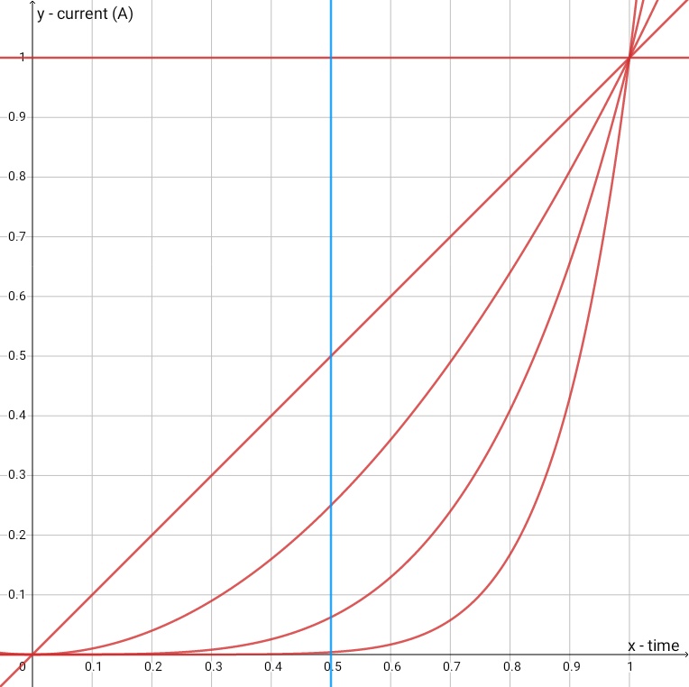
In a very, very, very large SIMPLIFICATION, an example of a power curve for five assist values looks like the picture below. Keep your distance from this graph. Chart Maker Pro is not very powerful and not very convenient to use. Well, the charts are quite legible. Start up to 100% as a function of time first, then the middle with a decrease at the end - as a function of the cadence (RPM). After we stop pedaling, I only follow the engine, but this is not included in the graph below.
So to the point. Here are my settings along with an explanation of why so and not otherwise. Sorry for a little chaos, but it's hard to describe one setting separately from the other. Enjoy your meal!
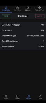
GENERAL
Low Battery Protection - 41V
A single li-ion cell should not discharge below 3V. 48V package is 13s, 13x3V = 39V. For me, the average voltage drops when powering back are usually around 2V, so 41V is the most healthy for the battery. I used to set 39V here, but the engine started to "stop" at 40V - this means that the controller would still wait with the engine off, but the battery BMS decided to work earlier.
Current Limit - 25A
I do not buy the strongest version of BBS02B for this, to limit its possibilities at the beginning. I'd rather tame his temper in a different way. I will do it for the first time in a moment, in the LEVELS tab. Besides, it gives me easy to imagine five booster steps - 5A, 10A, 15A, 20A, 25A.
In the Internet, I often read to limit the current (A), because we get it more than we set and it is dangerous for the driver. No. If we set here, for example, 18A, we get a maximum of 983W not because the controller controls a higher current (A), but because it has 54.6V of a fully charged battery at its disposal, and it does not work on a nominal 48V (which gives 864W) . When the battery voltage drops even more, the output is even less power (W).
Speed Meter Type - External, Wheel Meter
Speed sensor type. In my case, the sensor at the rear wheel.
Speed Meter Signals - 1
So far 1. As part of the experiment, I'm going to add a second magnet on the opposite side of the wheel and change this value to 2. In theory, this should increase the frequency of reading the bike speed and, as a result, SIGNIFICANTLY improve the smooth running of the engine - but only under certain conditions. My guess is that the display will not change much, because it updates the indications rather sluggishly. We'll see. I also have a second, different and rather less likely theory about how this setting works. So that it ignores a certain number of sensors on the wheel if there are more than 1. Useful when there is still a computer on the steering wheel, e.g. Garmin, Sigma, CatEye, etc.
Wheel Diameter - 26 inch
The size of the wheel. I am 26 ”. As a curiosity, I would like to mention that with this setting we can break the speed limit of the bike to 40 km / h. I do not do it, because in fact, even 30 km / h for me is a sufficient speed, at which I have such a high cadence that I think that I am about to fall off the bike. There are at least a few logical reasons why you should not raise your bike's speed limit. The most important of these is the one that says the BBS02B 48V 750W is just too weak to go crazy without hurting itself.
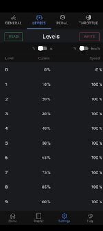
LEVELS
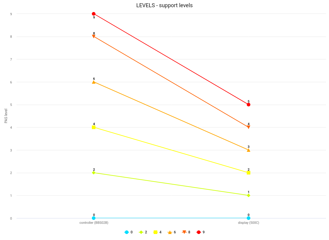
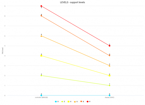
Level - 0, 1, 2, 3, 4, 5, [6]
I don't like changing help levels often. I like how everyone is as universal and "stretched" as possible. So I gave up 9 and set 5 help levels - but in fact I use 7 squares. The two additional ones are "0 - no PAS support" and "[6] - the throttle releases 100% current (25A)". Level 6 is inaccessible from the display, but the controller sees it and works according to the settings. This is exactly what the transfer of data from the Android application "Speeed" to five levels of 500C display support looks like. In the case of other models of displays, dependencies may differ and may look like this; 0 = 0, 1 = 1 2 = #, 3 = 2, 4 = #, 5 = 3, 6 = #, 7 = 4, 8 = #, 9 = 5.
0 = 0 - no PAS support, the throttle is working
1 = [6] - the throttle releases 100% of the current (A) and allows you to reach 100% of the engine speed (RPM)
2 = 1
3 = #
4 = 2
5 = #
6 = 3
7 = #
8 = 4
9 = 5
I don't know what this graph is for, probably just from the run-up. Or boredom.
 Current
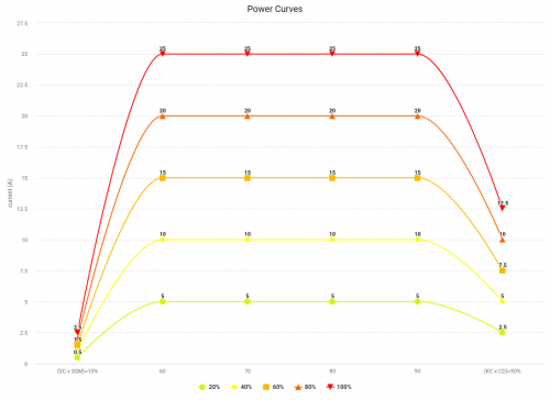
 - 20%, 40%, 60%, 80%, 100%
This setting tells you what will be the maximum current (A) that we will get at a given level of assistance. The curve that is the result of the "Start Current and Slow Start Mode" functions is going to this point and almost (because every rule must have exceptions) always reaches it. Even increments of the support make it easy for me to estimate what power (W) and under what circumstances (the same power (W) - cadence (RPM) dependence curve at each support level) I will get after changing the support level. Their linearity, hence - a certain stability, also helps in conducting experiments. If we want the throttle to work at the 0 support level at all, set the value of 1% here and in the "Speed" column - that's how someone came up with it.
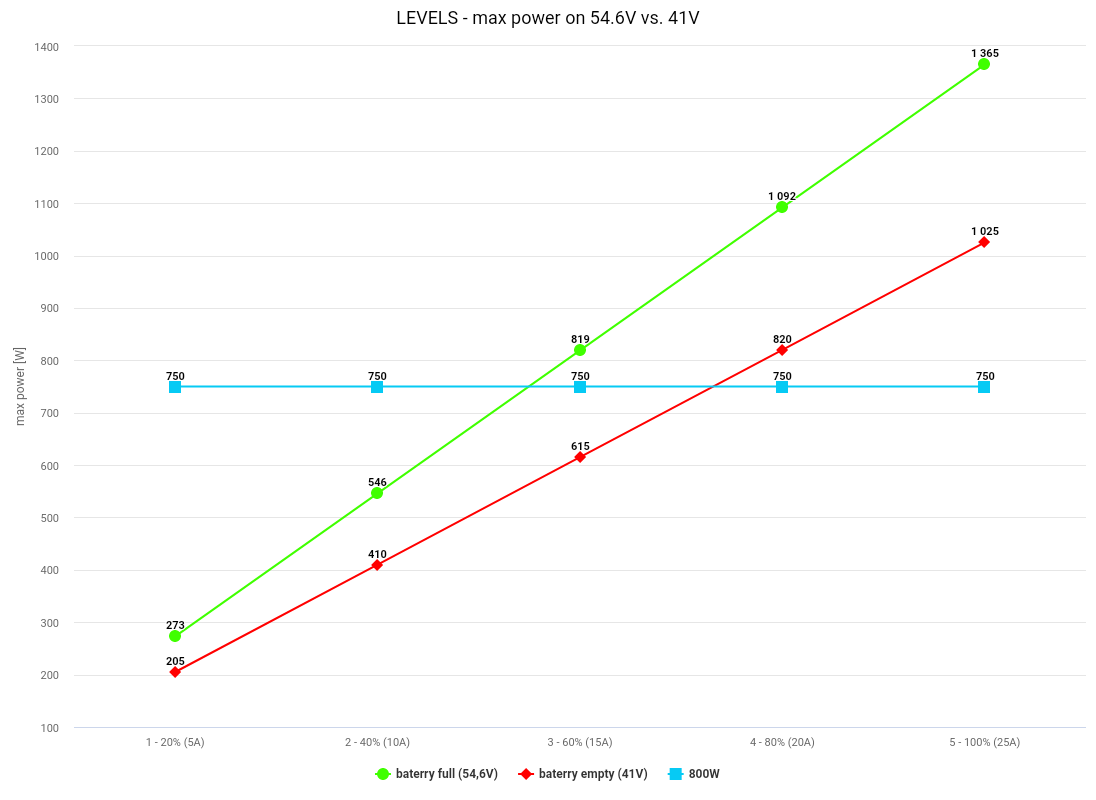
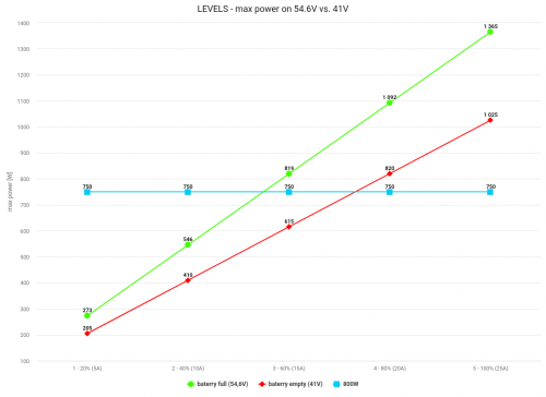
The powers below are the maximum powers we can achieve with a fully charged, well-designed battery. In fact, the power (W) achieved is lower. The maximum power (W) that we get at a given level of support is characterized by multiplication of 54.6V * xA and the course of the mid-end curve. This means that the lower the battery voltage, the less power we get (W). The same applies to voltage drops (V) with high current consumption (A) - they will be greater, the worse / more economical we design the battery. Material for the book. The smallest voltage drops (V) can be achieved with a capacious (Ah) battery, built on the largest possible number of high-current cells connected in parallel (p). The lower maximum range of available power (W) at a given support level is the result of multiplying the current (A) by the voltage (V) of the discharged / nearly discharged battery, i.e. 41V * xA.
The linear distribution of the maximum current, in cooperation with the relatively narrow (20-30RPM range) range of maximum cadences in the "Speed" column, gives a really very good feeling of control "in the leg" at each support level.
0 - 1% (0.25A) - no PAS support, the throttle is working
1 - 20% (5A) - 205-273W
2 - 40% (10A) - 410-546W
3 - 60% (15A) - 615-819W
4 - 80% (20A) - 820-1092W
5 - 100% (25A) - 1025-1365W
[6] - 100% (25A) - 1025-1365W - the throttle releases 100% of the current (A) and allows to reach 100% of the engine speed (RPM)
BBS02B 48V 750W, as the name suggests, is designed for a constant power consumption of 750W. There is nothing we should be afraid of for consumption at this level. The engine, if we let it spin, should be able to withstand it with a finger in the butt. In the case of my configuration, where the power curve (W) is also shaped by other settings, it means that I can drive without restraint and greater anxiety on all five levels of assistance.
 !!! Speed
 - 65%, 70%, 75%, 80%, 85%
!!!
If we want to ride a bicycle, not a motorbike - this is one of the MOST IMPORTANT, but also one of the most MISUADE understood settings. Here it is ALL about the speed of the engine / crank, not the speed of the bike! This should be a value in RPM, not KM / H! I don't know why this crap keeps getting duplicated in so many places !?
If we set 100% here, the engine will strive to reach the maximum engine / crank speed throughout the power curve, which in the case of the BBS02B 48V 750W under light load is around 2957RPM / 135RPM (21.9RPM / 1RPM). If I set here e.g. 70% (95RPM) then after the start-up stage, in most scenarios I will get the maximum current (A) at a given aid level, but when I get close to 95 crank revolutions per minute - the current (A) will start to drop to a percentage value specified in "Keep Current" in the "PEDAL" tab.
Below is a table with the specifications of the different versions of BBS01B, BBS02B and BBSHD. The maximum cadence under light load is the line "nT" ("n0" is the value without load - say without a string). The maximum engine speed is obtained by multiplying this value by the reduction factor, i.e. 21.9.
I used to try to keep this setting equal for each assist level, like 1 - 65%, 2 - 65%, 3 - 65%, etc. That would be great for me! However, this parameter is highly dependent on the battery voltage. If the battery has 54.6V, then e.g. 65% = 88RPM, but if the sleeping voltage is up to, say, 41V, the value is 65% ≠ 88RPM - only definitely, definitely, definitely less. I didn't like it. Especially when climbing. Subjectively, I believe that the BBS02B 48V 750W rotor does not like to spin, under load, in lower ranges than 60% (1774RPM / 81RPM) of its maximum RPM, and this is what happened with the falling voltage (V) of the battery.
The linear progression of these parameters on the following levels of support solved this problem and fits perfectly with the ideas of my settings. I have noticed that when the battery is charged, when I want to move slowly I am riding on assist level 1, but the more the voltage drops, the more likely I am to use higher assist levels to achieve a similar effect. Hypothetically, when the battery is charged, for example, on
level 3, I will get a maximum (54.6V * 15A =) 819W, but when it is almost discharged, to receive similar help, I have to use level 4, which will also give me in these circumstances maximum (41V * 20A =) 820W. You can see it well in the chart above - I added the "750W" line there to emphasize this fact even more.
It comes down to the fact that when I start driving, I use levels 1-4, and when I come home, it is more often already 2-5. This gives me the Illusion that I am not losing power with a flat battery. The best thing is that by choosing the parameters "Current Decay", "Stop Decay" and "Keep Current", despite the large differences in the maximum voltage (A) at a given support level - the motor handles the battery very gently, while being powerful, predictable and culturally support!
Dependencies 1-5A-88RPM, 2-10A-95RPM, 3-15A-101RPM, 4-20A-108RPM, 5-25A-115RPM result in the fact that on a flat (light load), each successive level of assistance increases the maximum speed bicycle, while in the case of hills (high load), they make the climb more efficient. Very intuitive.
Due to everything I wrote above, I believe that "Speed" is the MAIN parameter that can be tame, but not deprived of the maximum power (W) available at a given level of support of our Bafang. Everyone likes to turn the cranks in different ranges. Anyone who does not want to turn the crank in the air without resistance, trying to keep up with the engine speed, should realize their favorite / comfortable AND the maximum range of pedaling speed, e.g. just 90-120RPM in my case and write it linearly at 5, or 9 levels of support. If 100% is needed - the throttle remains. Attention! The lower we set the "Current Decay" and "Keep Current", the harder it will be for us to reach and maintain the planned term of office! On the other hand, if we do it, it will be more "cycling" and less zero-one.
Knowing the cadence that we will (almost) always achieve, it is easy to calculate the speed of the bike that will allow us to achieve a specific value of this setting. In my example - I have a 26 ”wheel, the average circumference of such a wheel is 2100mm (0.0021km). I have 32t discs in the front, IGH in the back - the equivalent of a 5-speed cassette with a span of 12-29t. It is enough to calculate the reduction ratio for the minimum speeds (32t / 29t = 0.90: 1) and maximum (32t / 12t = 2.67: 1), or just for the specific crown you are interested in and then multiply the result by the cadence ( RPM), rim circumference (km) and for 60 more, because that's how many minutes we have in an hour (h). So e.g. for the fifth level of support, on the crown 12t, the equation will look like this - 115 * 60 * 0.0021 * 2.67 = 38.7 km / h. The calculations are in line with reality.
Note that my gear range is relatively narrow. 12-29t in five steps is really not much and it does not allow me to use the full potential of the engine. Previously, I rode a 9-row cassette with a span of 11-46t, also with a 32t disc - the bike achieved higher maximum speeds and was able to climb vertical walls. Well, but I fell in love with IGH. Love can be irrational.
0 - 1% (1RPM)
1 - 65% (88RPM) 10-29.6km / h
2 - 70% (95RPM) 10.8-32km / h
3 - 75% (101RPM) 11.5-34km / h
4 - 80% (108RPM) 12.3-36.3 km / h
5 - 85% (115RPM) 13-38.7 km / h
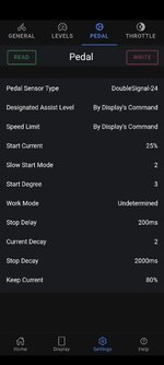
PEDAL
Pedal Sensor Type - DubleSignal-24
My BBS02B is equipped with this PAS sensor. There is no point in looking for a "better" setting here, as it won't get anywhere. At most, errors in the operation of the sensor.
Designated Assist Level - By Display's Command
At this point, you can set whether we will be able to choose the degree of support from the display level, or whether we want to set it rigidly, to a specific level in the controller. In my opinion, a choice is always better than not having one. Well, unless we lend someone a bike.
Speed Limit - 40km / h
This is the limit of the maximum speed a bike can reach, regardless of the engine / crank speed (RPM) achieved. After exceeding the counted speed, the same happens as in the case of exceeding the limit in the "Speed" column in the "LEVELS" tab - the given power is limited to the percentage value from the "Keep Current" setting. My current configuration (26 ”, 32t, 12t) at maximum engine speed (135RPM) would allow it to reach about 45.4 km / h. Of course, the maximum engine speed with the heaviest gear ratio can only be achieved under favorable conditions. 40 km / h is enough for me - the engines in the rear wheel are more suitable for breaking speed records.
Start Current - 25%
Now pay attention! At the beginning and after, I wrote that the boot section is a function of time. I was convinced of it! This may not be true. This section can also be based on tenure, but it was easier for me to count over time. After all, what I am trying to reproduce in the charts below, if it is written over time - is more intuitive to understand. The reason for my doubts was a specific "limbo" state, which can be achieved with a small current (A), "Start Current = 1%", "Slow Start Mode = 1", low values of "Current Decay" and low "Keep Current" value. It is possible to suspend the start-up stage and drag the entrance to the mid-end section for quite a long time.
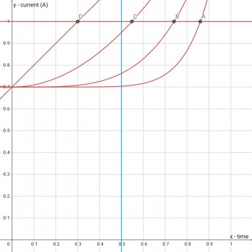
"Start Current" is the setting that determines what% of the maximum current (A) at a given assist level the motor starts from. The cooperation of this parameter with the "Slow Start Mode" determines how quickly and how we get the maximum current (A) at a given level of support.
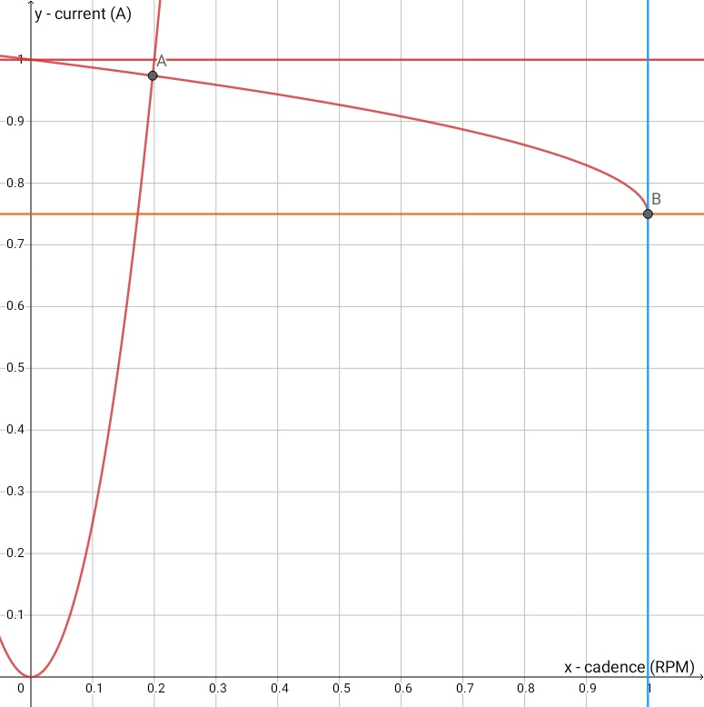
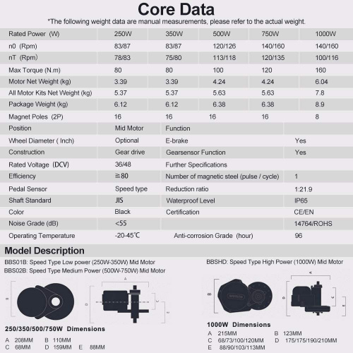
According to my observations, this is what the curve looks like (and in the case of "Slow Start Mode = 8", i.e. in this particular case - simple or almost straight) of the increase in power depending on the% of starting current (A). The y-axis is the% of the starting current (A) (1 = 100%), the z-axis is the time it develops (without the unit, because I did not conduct precise measurements, but by setting 25% here, I get the maximum current after about 5 seconds - without much due to the "Slow Start Mode" value). The graph clearly shows that the more% we set, the faster we reach the maximum available current (A) at a given level of support. What happens with the current (A) on the way to the maximum is a completely different matter.
 Slow Start Mode
 - 2
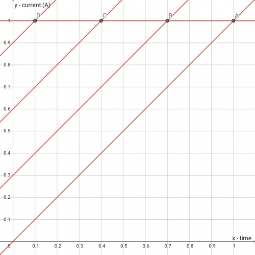
This is a parameter that, according to my observations and feelings, shapes the current rise curve (A). While at low "Start Current" values, it (almost) always reaches its maximum at a similar time, along the way, depending on the set value - it happens in a different way. To show it well, I added a blue line in the charts below. While the current (A) after 100% of the time reaches its 100% at a given level of support, it differs in ½ of the time needed to reach the maximum, depending on the value set here.
The value of 8 seems to be close to the straight line. The closer we get to the value of 1, the more the starting current (A) grows after a larger parabola. At least that's what I felt changing this parameter and keeping the "Start Current" constant. There are four examples in the graphs.
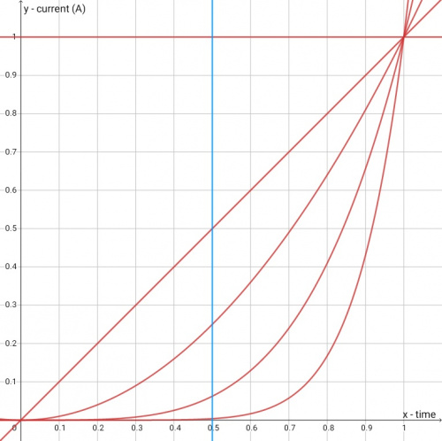
The next charts show the same, only starting from 30% and from 70%. The offset may and most likely looks a bit different than in the graphic below, but I haven't found a simple formula for it yet, so the "less developed" version of the chart below must suffice for you and for you. It is clearly visible here that depending on the "Slow Start Mode" value set, the higher the "Start Current", the greater the difference in time to 100% of the current (A) will be experienced.
Finally, why did I choose 2? Despite the set engine start after only 45 ° crank rotation, it gives me enough time for, for example, adjusting the gear ratio, or small maneuvers that do not require a lot of support. Thanks to the low "Stop Delay" value, I can also quickly release the start without suddenly jerking the engine. At "Start Current = 25%" this gives a responsive and very natural starting effect.
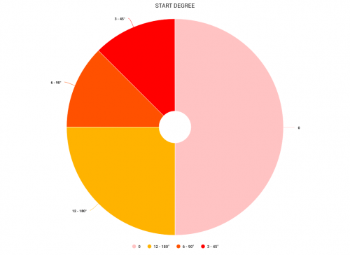
Start Degree - 3
The PAS sensor on the BBS02B has 24 fields. They give a full circle - 360 °. I set the lowest non-error value 3. This means I need to make the engine run (45 °) one full crank revolution. I like when the engine reacts quickly to what I am doing. This applies to both starting and stopping.
If we set 2 here, everything works fine as long as we turn the crank forward. If I start spinning backwards, the engine starts kicking forward in an unpleasant way. I can guess why this is so, but it is so insignificant to me that I do not want to fray the keyboard. I'm sorry.
"Stop Delay" also has a significant influence on the operation of this setting. Each subsequent sensor field to be "passed" must fit within the time interval (ms) of this parameter. It comes down to the fact that the lower the value (ms) we set here, the faster (RPM) we have to crank the crank to start the engine.
The bill is simple. If we set here, for example, 6 and "Stop Delay" to 100ms, then for the engine to start, we need to make a 90 ° turn of the crank in at most 0.6s. If we set here 6 and "Stop Delay" to the popular 250ms, we already have 1.5 seconds for the same crank movement. In practice, with a higher value (ms), it is easier to provoke the engine to start under load - uphill or in too heavy a gear. It is also easier to start the engine when we did not plan it, e.g. by standing next to the bike or by guiding it and accidentally rubbing the crank.
 Worki Mode
 - Undeterminated
In theory, this could be an important setting. In theory, it should be most helpful and noticeable for large and fast CHANGES in bicycle speed, while maintaining a constant, high cadence (RPM), in situations such as a quick reduction of the gear, during increasingly steep climbing. In theory, in such situations, it should delay the need to switch to a higher level of assistance. In practice, I have not yet studied this parameter. Maybe someday?
You can help me with this, because I got a lead. In the case of BBS02B, I can set a maximum of 70 here. After that, an error pops up. I am curious if the BBS01B accepts a setting of 70 and whether the BBSHD crashes with a setting of 80. After gaining this knowledge, I will be able to think further.
Stop Delay - 100ms
This parameter, apart from what I described above, primarily determines how quickly the engine stops working after you stop turning the crank. As I wrote before - I like when the bike reacts quickly to what I do. The 100ms setting works fine with the rest of my settings. Below 100ms, the support on the BBS02B does not work properly.
Current Decay - 2
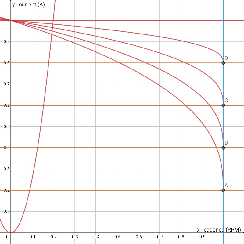
Here we decide what the curve of the decrease of the current (A) looks like, progressing with the increase of the cadence (RPM). This parameter, together with "Keep Current", decide WITH WHAT EFFORT, and thus - how fast (and if at all) - we reach 100% of the maximum cadence (RPM) set in "Speed" in the "LEVELS" tab.
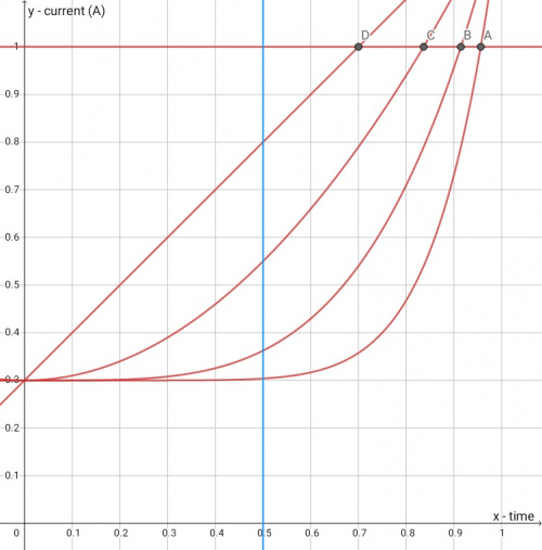
The lower the value we set here, the smoother the slope curve will be. The closer to the value 8 (but also the closer to "Keep Current = 100%"), the more zero-one the whole system works. The more "copies" when crossing and returning from the line (this is the blue line) of the maximum cadence (RPM), which we set in "Speed", in the "LEVELS" tab. One image is supposed to be a thousand words. Below are some sample "Current Decay" values. The orange line is "Keep Current = 50%".
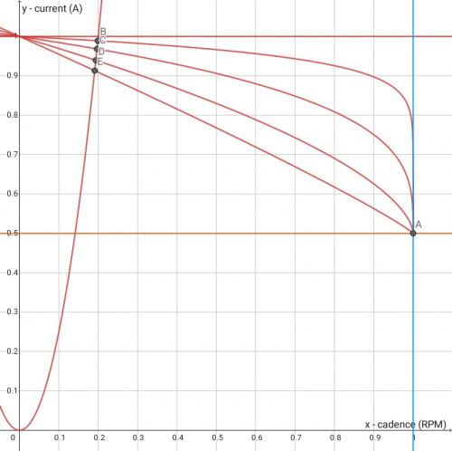
If we combine a low value of "Current Decay" with a low value of "Keep Current", there is a high probability that it will not allow us to reach the maximum current (A), and thus it will be harder for us to reach the maximum cadence (RPM) set in "Speed" ) at a given level of support. Sometimes it may even be impossible. At low values of both settings, it will be very "cycling", but we can silt our system so much that it will not be able to significantly support us. A compromise has to be found between these two parameters. As I tested individual variations of these settings, I found that one likes to oppose the other. For example, "Keep Current = 20%" works well with "Current Decey = 8", and "Keep Current = 80%" works pretty well with "Current Decay = 2" - such configurations prevent system silting. So they do not drastically reduce the current (A) with increasing cadence (RPM). In my opinion, the first option is good for hard and smooth roads. The second is a mixed terrain, the slope of which changes a little more sharply.
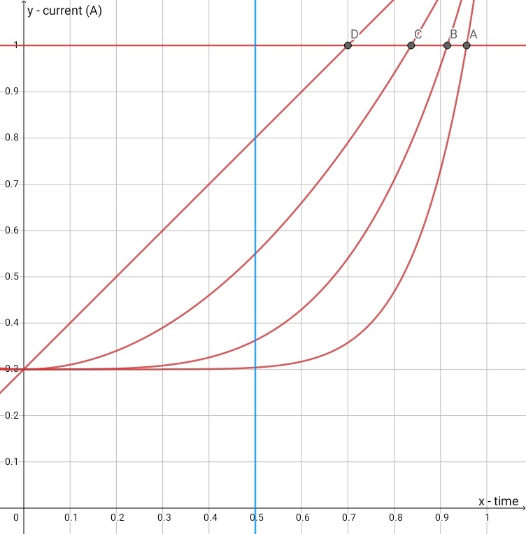
Earlier I wrote about the fact that the current (A) after the start-up stage ALMOST always tends to its maximum at a given level of support. This is the place to explain why he doesn't reach his maximum sometimes. The maximum current (A) we get at a given support level is most likely due to the point where the start-up and mid-end curves intersect (B, C, D, E in the figure above). With this parameter, it is more convenient to look at the starting curve as if it were performed as a function of the cadence (or maybe it really is?). At least, this is how I feel - and I'm experimenting, without respite, already over 1000 km. To paraphrase the classic - in this matter I have a conjecture bordering on certainty. Which, of course, does not mean that it is for this particular reason.
With "Keep Current = 75%" I chose the setting 2. It makes it relatively easy to reach my target cadence (RPM), and after exceeding it, the power is not drastically limited. I have some gains in the region and this allows me to overcome them efficiently. If I rode mostly flat, I would set Keep Current to around 50% and Current Decay to 4 or more. This is how I feel more or less at home.
 Stop Decay
 - 2500ms
In my opinion, this setting has little (if anything) to do with "Stop Delay". I did not notice any relationship between these settings. It seems to me that for the time specified here, after exceeding and returning from above our maximum cadence from the "Speed" setting, this parameter limits / smoothes the re-gain (A) shaped by the "Current Decay" and "Keep Current". It's easiest to see the effects of this setting at high power levels and a light gear ratio. In short - it eliminates the "kick" of the assistance when moving around our maximum cadence. The lower we set the "Current Decay" and "Keep Current", this parameter becomes less important for us, because such a configuration often does not allow us to reach and exceed the target cadence.
That's just a word of introduction, because because of this fuc***g pandemic, I don't have a chance to explore it further. So far, I have set 2.5s here and have not noticed any negative side effects, such as limiting the maximum speed of the bike. But it "kicks" less noticeably.
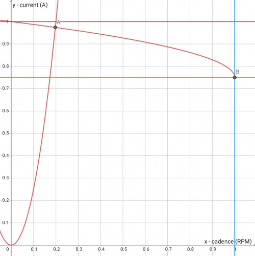
Keep Current - 75%
Here we decide to what level the current (A) will drop, after exceeding the maximum cadence from the "Speed" setting. As I wrote before, due to the fact that this parameter works very closely with the "Current Decay" - these settings should not be considered separately. Below is a graph of what the same "Current Decay" looks like depending on the different "Keep Current" settings. Let me repeat, 75% turned out to be good for me - they will not kill the motor's potential, but it is far enough from 100% that the low Current Decay values can be nicely smoothed and civilized.
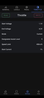
 THROTTLE
Start Voltage - 1.1V
End Voltage - 4.2V
Mode - Current
Designated Assist Level - 1
Speed Limit - 40km / h
Start Current - 1%
I use the throttle really sporadically, so I will not devote too much space to the description of its parameters. The above settings make it run very smooth and it's far from zero-one work. If I feel like it, it triggers around 1300W. I move at the pace of a stroller if I feel like it, using less than 100W.
And that would be it. In the future, depending on my free time and willingness, I will try to dig even more into the issues of "Work Mode" and "Stop Decay". I will be very happy with any kind of criticism and discussion. Greetings!