Adding a Rotary Dial Speed Control

The PAS system reacts to changes in pedal pressure which cause current spikes. With PAS, when you pause pedaling and resume again or change the amount of pedal pressure, there is a current spike. These spikes waste energy.
Another good reason to avoid spikes on an ebike.
 
Wow! What a reply! Thank you!!
My throttle has multiple wires but according to your diagram I only need to identify the +, -, & signal wires. (3 total) Is that correct?

Here's some more info that should help you identify the wires.

Screenshot_20221112-151304_DuckDuckGo.jpg
Screenshot_20221128-170934_Gallery.jpg
Screenshot_20221128-145418_DuckDuckGo.jpg


I used @6zfshdb 's idea and information and managed to hook up two throttles to my ebike.

Then I switched out my controller to a KT controller and display. When I turned on my display my throttle didn't work and I got an error code.
I swapped the positive and negative wire and I no longer got the error code, but my throttle still didn't work.

I'm pretty sure that the position of the 2.2 k ohm and 2.7 k ohm resistors is what caused my problem.

I switched the polarity of my throttles, but not the position of the resistors. (which isn't possible with the throttle itself.)

Fortunately I had a third thumb throttle that works, and my new KT controller/display has cruise control, so I don't need the Auxiliary cruise control box.

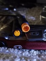
I found out that regular throttles come with both male and female 3 pin julet connectors, and I'm pretty sure that the only difference is the pin configuration and what resistor connects to what pin.

20230318_223647.jpg
 
Care should be used when making any connections to the throttle circuit. Wiring faults can cause the bike to go full throttle unexpectedly.

If the project becomes too difficult, you can always use this product on your twist throttle instead:

51I4sL7ZwUL._AC_SL1000_.jpg


It's primarily used on motorcycles but it works on e-bike twist throttles as well. It provides the same cruise control effect but requires some adjustment to change speeds.
 
Last edited:
Here's some more info that should help you identify the wires.

View attachment 149614View attachment 149615View attachment 149616


I used @6zfshdb 's idea and information and managed to hook up two throttles to my ebike.

Then I switched out my controller to a KT controller and display. When I turned on my display my throttle didn't work and I got an error code.
I swapped the positive and negative wire and I no longer got the error code, but my throttle still didn't work.

I'm pretty sure that the position of the 2.2 k ohm and 2.7 k ohm resistors is what caused my problem.

I switched the polarity of my throttles, but not the position of the resistors. (which isn't possible with the throttle itself.)

Fortunately I had a third thumb throttle that works, and my new KT controller/display has cruise control, so I don't need the Auxiliary cruise control box.

I found out that regular throttles come with both male and female 3 pin julet connectors, and I'm pretty sure that the only difference is the pin configuration and what resistor connects to what pin.

View attachment 149618
Whoa! That is some fantastic information! Thank you! I suspect others will be just as appreciative as myself! This is like getting a degree worth of information! Perhaps everybody knows this stuff and I'm just naive but for my situation, it is pertinent.
 
Care should be used when making any connections to the throttle circuit. Wiring faults can cause the bike to go full throttle unexpectedly.

If the project becomes too difficult, you can always use this product on your twist throttle instead:

View attachment 149634


It's primarily used on motorcycles but it works on e-bike twist throttles as well. It provides the same cruise control effect but requires some adjustment to change speeds.
I checked out the reviews and concluded I would pass for now but I did make a homemade cruise control using the corner of a plastic hanger that I saw on YouTube yesterday and it works pretty good! Thanks for the suggestion; I'm game to trying your control box ☺
 
Perhaps everybody knows this stuff and I'm just naive but for my situation, it is pertinent.
I don't think it's common knowledge. I just figured it out by trial and error starting with 6zfshdb's diagrams.

I just hooked up two throttles in parallel. +5v to +5v, negative to negative, and signal wires connected together and it worked.

Which ever throttle was turned up the highest overroad the other.

The +5v powers all the sensors, the display, and both throttles (or the potentiometer). If the controller ever sees less than ~0.8v or more than ~4.1v it registers a code and disables the throttle.

On my ebike, if I had a throttle left on when I turned on the ebike, the throttle was ignored and didn't take off.
Simply turning it to zero then back on reset it.

Most throttles are Hal sensors with magnets inside, but some throttles use a precision variable resistor/potentiometer.
 
It provides the same cruise control effect but requires some adjustment to change speeds.

So if you want to decrease the speed, you just twist the throttle slower and the clamp should self adjust.
Provided that you didn't clamp it down too hard.

When it comes time to increase your speed, you twist the throttle more and the "cruise clamp" lifts off the brake handle.

That's when you reach across with your left hand, and push down on the "cruise clamp" on the right handlebar to reset the clamp.
You can't let go of your right hand because the throttle is spring loaded.


If you want to see what it's like, try reaching across with either hand to the opposite hand grip, and push down 👇 lol
With a little practice, the clamp can be adjusted with your throttle hand without without taking it off the grip. Not as easy as turning a knob but it's better than nothing.

On some bikes, you need to take one hand off the bars to make adjustments unless the control is placed convenient to one of the grips. I placed mine this way so I can adjust speed, switch between throttle, cruise control or off, all with my thumb without taking my hand off the grip:

1679313639192.png


Control placement is important with a project like this.
 
With a little practice, the clamp can be adjusted with your throttle hand without without taking it off the grip. Not as easy as turning a knob but it's better than nothing.

On some bikes, you need to take one hand off the bars to make adjustments unless the control is placed convenient to one of the grips. I placed mine this way so I can adjust speed, switch between throttle, cruise control or off, all with my thumb without taking my hand off the grip:

View attachment 149755

Control placement is important with a project like this.
Nice set up!
I asked the supplier for my Violamart kit which wires were + - signal. This is their response. Translation into English might have lost something. How do you interpret it for the control box config?
Brown : The power Ⅱ
Yellow: Power display
Green:The electric door lock
Red :Turn to 5 v
White:Turn the signal
Black:Ground wire

PS. I'm gonna try the cruise control I made watching a YouTube video from a plastic clothes hanger this week and see how well it performs.....
 
Cool 😎 You've got doors on your ebike. 😂

It's probably the red white and black wires that you need.
The brown wire probably turns on (+5v) when you turn the key to on? If you have a key.

And you can lock your doors with the green wire. 😂
 
Or, the brown wire is always live (+5v) and the red wire turns on when you turn on your ebike.

The brown wire may be battery voltage, and you don't want that.

Check the voltage of the brown and red wire relative to the black wire.
 
Cool 😎 You've got doors on your ebike. 😂

It's probably the red white and black wires that you need.
The brown wire probably turns on (+5v) when you turn the key to on? If you have a key.

And you can lock your doors with the green wire. 😂
No key but a button under the throttle that turns it on/off.
 
No key but a button under the throttle that turns it on/off.
It's probably the red white and black wires that you need to use.

The red wire probably "turns to 5v" when you turn on your bike.
Then your signal wire (white) turns on as well.
 
PS. I'm gonna try the cruise control I made watching a YouTube video from a plastic clothes hanger this week and see how well it performs.....

That certainly is an easier option.
And you should easily be able to adjust it safely with one hand.
It's just a little tacky looking, but as long as it works and isn't a safety issue.

I would have done that myself but I didn't have a twist throttle on my ebike at the time.

I had to tape my throttle open while holding a brake lever on to kill the motor.
That was a bit dangerous. I had to use both hands to tape the throttle open.
 
Care should be used when making any connections to the throttle circuit. Wiring faults can cause the bike to go full throttle unexpectedly.

^^^ What he said.
@Rice Bike
I should add, that I managed to connect 2 throttles together in parallel and it worked on my ebike.
That may not be the case with every ebike.

6zfshdb's design is safer in that it completely removes the throttle from the circuit before engaging the cruise control circuit.
And the switch for it is easy to hit with your thumb to turn it off in an instant.
 
I use the rotary speed control on bikes with 30A controllers and have had no issues. The motor wattage should not be a factor. The controller has to be configured for a 3 wire throttle however. The resistor values should work with most controllers that use the 3 wire standard.

Parts list:

2.7 K ohm resistor: https://www.amazon.com/gp/product/B07WGMKTQB/ref=ppx_yo_dt_b_search_asin_title?ie=UTF8&psc=1

2.2 K ohm resistor: https://www.amazon.com/gp/product/B07WGMZ7ZD/ref=ppx_yo_dt_b_search_asin_title?ie=UTF8&psc=1

1 K ohm potentiometer: https://www.amazon.com/gp/product/B074KGJ7N6/ref=ppx_yo_dt_b_search_asin_title?ie=UTF8&psc=1

Plastic case: https://www.amazon.com/gp/product/B07Q11F7DS/ref=ppx_yo_dt_b_search_asin_title?ie=UTF8&th=1

3PDT Switch: https://www.amazon.com/gp/product/B07VHC9LYG/ref=ppx_yo_dt_b_search_asin_title?ie=UTF8&psc=1

6 conductor 22 GA wire: https://www.amazon.com/gp/product/B07Y33WL43/ref=ppx_yo_dt_b_search_asin_title?ie=UTF8&psc=1

I used the raw ended wire above to cut and splice into my wiring harness but you may be able to find pigtail connectors that will fit those used on your bike. These are a possibility:


I used these handlebar clamps for a mount but there are many cheaper alternatives:


Please note that most of the parts listed above are quantity purchases since I made up several speed controls. You may be able to find them individually and save some money.

Welcome to the forum and good luck with your project!
The manufacturer of my eBike kit tells me that my controller is between 26-30 Amps so I guess mine falls into the category you mention. I have a question. How did you come up with those values for your resistors and potentiometer? I will use the same because you have the prototype but I was just curious. From my perspective, you're no less than a genius. Must have been loaned to you from Heaven's allotment. <><
 
The manufacturer of my eBike kit tells me that my controller is between 26-30 Amps so I guess mine falls into the category you mention. I have a question. How did you come up with those values for your resistors and potentiometer? I will use the same because you have the prototype but I was just curious. From my perspective, you're no less than a genius. Must have been loaned to you from Heaven's allotment. <><
No genius, just a retired electrical engineer with too much time on my hands 🙄

The circuit is just a simple voltage divider. The resistor values are based on the measured impedance of the hall sensor circuit. You can also use an ohmmeter to measure the resistance on most 3 wire throttles since they all seem to follow the same loose standard.

The resistors I used work best with my particular controller / motor combination and should give acceptable performance on most others. You can play around with the values a bit to fine tune the performance of the circuit for other bikes. I have mine adjusted so the max speed is slightly less than full throttle and the minimum is around 4 MPH. That way, I can use it as a walk assist for walking the bike up steep slopes or even stairs.

If you can find a connector that matches the throttle on your bike, I would "breadboard" the circuit first and test it before assembling the case and cutting into your wiring harness.
 
I occasionally get a cramp in my right hand when using my half grip twist throttle. As a remedy, I built this small control box as an alternate way to adjust speed. In doing some research, I discovered a 3 wire hall effect throttle can be emulated with a variable resistor. I wired the control box as shown:

View attachment 102769 View attachment 102766 View attachment 102767


I mounted the box on the left side near the display so it can be operated without taking my hands off the bars. It could be mounted almost anywhere however:

View attachment 102768

I used a triple pole double throw switch with a center off position. That way, I can change between the OEM throttle operation and the rotary control. The center position is off. The brake motor cut off and PAS systems are unaffected.

The 3 wire hall effect throttle is fairly standard in the industry and this idea should work on many different bikes.

Some soldering skills are required for the project since it requires cutting & splicing the throttle cable. The parts are all readily available from Amazon and I can provide a list if anyone is interested.
Hi, 3 pole switches can be harder to get and a little more expensive. Would it not be posible to form a common ground and use only a 2 pole switch?

Cheers Bird
 
Hi, 3 pole switches can be harder to get and a little more expensive. Would it not be posible to form a common ground and use only a 2 pole switch?

Cheers Bird
See my cruise here
 
Back