Soldering a live battery

Slowcycles

New Member
We have a 36v battery where the power wire broke off at the base. See https://photos.google.com/u/1/photo/AF1QipMcrNN4x6X8C5sqmn9U3szPrnuKN2yP28unu8d0 for a photo. The battery is showing full charge. How does one solder a new wire on the battery while it is charged? Any danger (other than the obvious)? Would one insert a pin first, or just hold the wire on the broken spot and add solder?

I live in an area where finding an expert is difficult. While I know how to solder, I've never worked on batteries, much less charged ones.
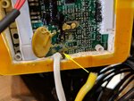
battery cable.jpg
 
While I`m not any kind of expert on anything but looking at the picture first i would try to clean as much as possible before applying generous dose of your favorite flux and than make a fresh spot of solder, now do same to the end of the wire, once cooled add a dab of flux and melt the two together, using flux will make sure that you get a clean solid bond between the two parts.
 
Yellow wire broke off? The right way to fix that is to get all of the remaining wire bits and solder out of that hole. Then you re-strip the old wire and insert it into the hole before re-soldering. Best way would be to take it all apart so you can heat the spot and push the broken wire out. The wire is also best resoldered with heat on the opposite side.

Otherwise, you have a surface joint that will have no strain relief and be very weak, and also is kind of tricky to solder.

Can't see the rest of the circuit or the other battery attachment points so cannot comment as how you can solder it safely with live cells. That looks like a BMS card and those have to be soldered to live cells when connected.
 
While I`m not any kind of expert on anything but looking at the picture first i would try to clean as much as possible before applying generous dose of your favorite flux and than make a fresh spot of solder, now do same to the end of the wire, once cooled add a dab of flux and melt the two together, using flux will make sure that you get a clean solid bond between the two parts.

Please make sure you use Rosin core solder and NOT acid core solder. Acid core solder is used for plumbing work and NEVER electronic work ..Now
on to the actual connection.

I can't figure out what the beige colored 'stuff' is where your arrow is pointed. That does not look good ! I'm concerned that during an attempt to re-solder
you'll risk overheating the immediate surrounding area of the beige 'stuff', lift the adjacent circuit traces and most likely ruin the circuit board... Note "U5",
the square to the right of the connection point. "U5" is a 20 pin microchip. They don't like heat . If you're able to re-solder without damaging the circuit board
my next concern is a high resistance aka a cold solder joint which you definitely do not want in you main power feed.
 
I thought the beige stuff is oxidized copper wires. Maybe some sparking as the wire degraded. That never resolders well.
 
I have a Background in working with Printed Circuit Boards, and you're Definitely going to need to Remove the board to get to the Foil side of it. Cleaning the remainder of the wire out, Refluxing the hole , and pretin the wire with Flux and Rosin core Solder before resoldering the wire in the mounting hole. This requires some time and Patience to do it right. ?
 
I have a Background in working with Printed Circuit Boards, and you're Definitely going to need to Remove the board to get to the Foil side of it. Cleaning the remainder of the wire out, Refluxing the hole , and pretin the wire with Flux and Rosin core Solder before resoldering the wire in the mounting hole. This requires some time and Patience to do it right. ?
I also forgot to mention, NO More than a 20 Watt pencil should be used ! Preferably a ESD rated pencil to prevent component damage !
 
I also forgot to mention, NO More than a 20 Watt pencil should be used ! Preferably a ESD rated pencil to prevent component damage !
Very helpful... and it sounds like it is beyond my skill level. Time to find a circuit board expert.
 
Your task Doesn't require an Expert, but does require some patience. The hardest part is probably going to be Removing the board. Once that's done, Cleaning out the previous wire, and prepping the mounting holes, Stripping the wire and reinstalling it in the board is only about 10 minutes work. ?
 
Having no idea what the entire pack looks like, I do fully agree that the board has to be accessed from the foil (trace) side.
Frankly, I doubt I would even try to fix that, again not knowing what the entire unit looks like.

How about a overall photo?
 
Back