Problem with KT-LCD8H

BarryofPhoenix

New Member
Region
USA
I installed a 35a controller and KT-LCD8H on my 2 year old radwagon. The only time the speedometer works is when the moter is not engaged. Any ideas? Photo are my settings.
 

Attachments

  • F1C64A14-FFA9-42BF-A4F1-E73839F16F0F.jpeg
    F1C64A14-FFA9-42BF-A4F1-E73839F16F0F.jpeg
    271.5 KB · Views: 476
I installed a 35a controller and KT-LCD8H on my 2 year old radwagon. The only time the speedometer works is when the moter is not engaged. Any ideas? Photo are my settings.
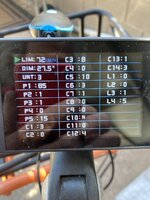
I would diagnose the pin-out for the speedo, make sure there is no brake in the wire and making a good connection. Since this is a non original controller,it is possible the pinout is different for the speedo. Do others have success with this controller on the Radwagon?
 
When the motor is engaged, the KT controller can figure the speed since it's spinning the motor. If it's a geared motor, the KT controller has no motor signal when coasting, so it switches to the speed sensor.

You set P2 to a nonzero value to tell the LCD that you have a speed sensor. The value of P2 is how many times the sensor flashes per RPM, This is often 1, but some bafang motors use 6. Your P2 probably needs to be 6, but it were working you would get a speed, just 6X higher, so there must be a connection problem.

Is this a plug-n-play KT controller with the same big motor connector on both the new controller and the motor? That should pick up the speed sensor connection automatically, if your motor has one.

If you had to do re-wiring of the above motor cable, the speed sensor wire in a bafang cable is the white wire, It shares the power on the red/black wires that are used by the Hall sensors. If by chance, the speed sensor on your motor got burnt out (it has happened to me), you can install an external one on the wheel.
 
I installed a 35a controller and KT-LCD8H on my 2 year old radwagon. The only time the speedometer works is when the moter is not engaged. Any ideas? Photo are my settings.
USUALLY the concern is opposite this, where the speedo works when under power, but quits/goes to -0- when coasting. That's opposite of what I'm understanding you to say above, which would be a new one on me.

No need to do a "pin out". KT uses the white wire in the motor side of the harness for speedo signal.

It's been my experience that the newest generation of Bafang motors have relocated the speed sensor to eliminate the need for a remote sensor required on the older motors - the ones with a part time signal that quits when coasting. The older motors generally get an external sensor to fix the problem.

Sorry to repeat much of what you said Harry. Didn't see your post until I posted. -Al
If op has waterproof connections, the "white wire" will not be visable, which is where a pin-out diagram is needed. Obviously you don't need a pin-out diagram for non water proof !
Outside the box is where all the ideas are hiding.
 
You can always take the lid off the controller and put a pin thru the white wire inside the box if you cannot otherwise reach where it lands on the circuit board.. Put a volt meter probe on the pin, referenced to ground. Power up the conroller. Spin the wheel backwards slowly and see if there is a 0-5V "waveform".
 
You can always take the lid off the controller and put a pin thru the white wire inside the box if you cannot otherwise reach where it lands on the circuit board.. Put a volt meter probe on the pin, referenced to ground. Power up the conroller. Spin the wheel backwards slowly and see if there is a 0-5V "waveform".
Yes , which is exactly what I was saying when I posted :
diagnose the pin-out for the speedo
What if the problem is in the water proof connector it self? Opening the controller will not find that.
 
Last edited:
Yes , which is exactly what I was saying when I posted :

What if the problem is in the water proof connector it self? Opening the controller will not find that.
Your right. You win. Lets move on, shall we?
 
I had a similar issue. Adjusting the P2 setting worked for me. I have a Ride1Up 700. I have mine set to 5 and the speed is displayed accurately now.

In the P2 setting, try each value. One of them should work.
 
Back