Hi folks,
I'm doing an e-bike conversion on my wife's Schwinn trike. First, a little history on the bike:
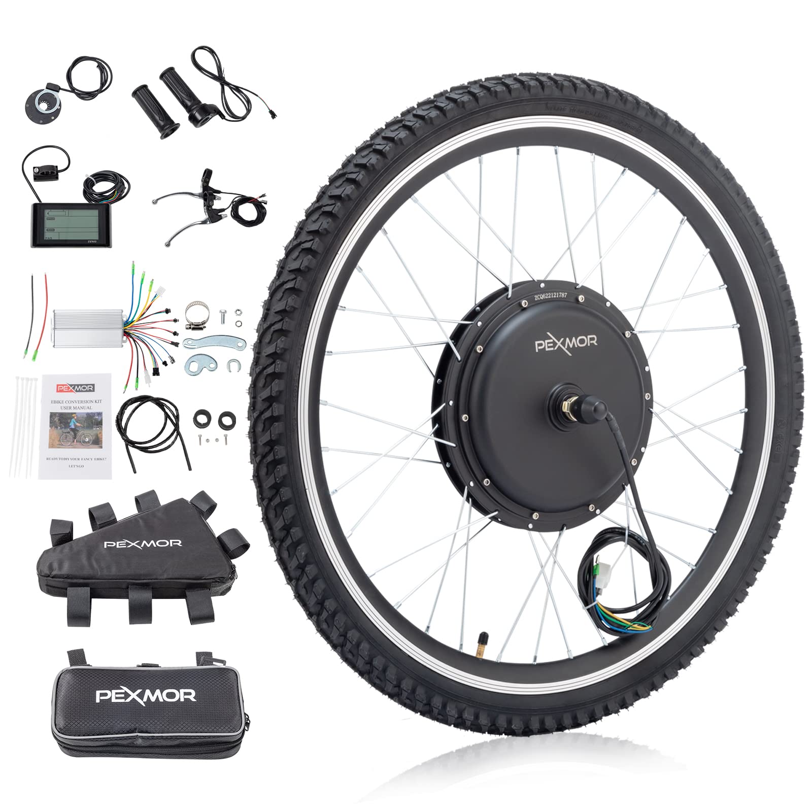
We got the trike a 4 or 5 years ago because my wife wanted to ride but she was a little too unstable to use a 2-wheeler, and she just loved it. It was great that we could all ride together again. That bike only had one speed, and we live in Colorado where it's hilly, so I put a 5 speed derailleur and cassette on it. I had to do some modification of the intermediate hub because it was too short for a cassette. I shortened it on the lathe, welded it back together, and it's been working great. I had to change the final drive ratio a little as well, but no biggie there. Works a treat. Recently we went on a little vacation where we had to rent a e-bike for my daughter, because she sprained her ankle the day we were to leave, and we still wanted to ride around. Anyway, the e-bike worked great. So great, in fact, it had me thinking the trike needed an upgrade. A little help up those longer hills would be wonderful. But, before I added more "go", I had to add more "stop". That trike has regular brakes up front. I don't know what you call that kind of brake. Old school... calipers grabbing the wheel rim. Front brakes work just fine, but the rear brake is a band brake that is absolutely worthless. I can ride that down the street, grab that handle with all I have, and barely notice slowing down. Worthless. So I took off that drum and put on a 140mm disc with mechanical caliper. It's not great, but it's ALOT better than the drum. I'm satisfied with the additional stopping power now. So I started installing this kit:

 www.pexmor.com
I got part way through the installation, and I looked at the motor controller and it didn't look weatherproof to me. That bike is stored indoors, but sometimes it gets caught in the rain, so I wanted to make sure a little rain wouldn't hurt it. I sent a question on Amazon (where I bought it) to the seller who said the controller was IP67, but it was ill-advised to use it in the rain. I replied with suggesting that IP67 should be rain - proof, or at least rain - resistant enough for me, so could they tell me what about the rest of the kit, it is all IP67, or will an occasional rain shower ruin it?
The connectors certainly don't look rain proof at all, but I can fix that, not worried about that at all. I'm really more concerned with things like the display, throttle, etc.
I cannot get them to answer. I also emailed Pexmor, and they haven't got back to me yet, a week later. So here I am, asking anyone here who might know if that kit can be used in the rain. Or should it specifically not be. Is it reasonably weatherproof or should I send the whole kit-n-kaboodle back and get something else? I am not against sending it all back. I just don't want to make a dumb mistake.
Thanks for reading my way - too - long question!
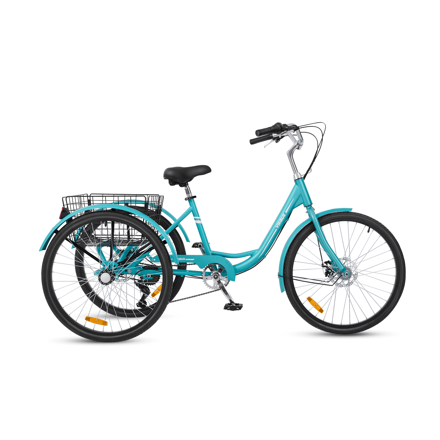
PS: I noticed a more modern version of her bike already has disc brakes and a derailleur. I should have sold that intellectual property to Schwinn

 viribusbikes.com
I'm doing an e-bike conversion on my wife's Schwinn trike. First, a little history on the bike:
We got the trike a 4 or 5 years ago because my wife wanted to ride but she was a little too unstable to use a 2-wheeler, and she just loved it. It was great that we could all ride together again. That bike only had one speed, and we live in Colorado where it's hilly, so I put a 5 speed derailleur and cassette on it. I had to do some modification of the intermediate hub because it was too short for a cassette. I shortened it on the lathe, welded it back together, and it's been working great. I had to change the final drive ratio a little as well, but no biggie there. Works a treat. Recently we went on a little vacation where we had to rent a e-bike for my daughter, because she sprained her ankle the day we were to leave, and we still wanted to ride around. Anyway, the e-bike worked great. So great, in fact, it had me thinking the trike needed an upgrade. A little help up those longer hills would be wonderful. But, before I added more "go", I had to add more "stop". That trike has regular brakes up front. I don't know what you call that kind of brake. Old school... calipers grabbing the wheel rim. Front brakes work just fine, but the rear brake is a band brake that is absolutely worthless. I can ride that down the street, grab that handle with all I have, and barely notice slowing down. Worthless. So I took off that drum and put on a 140mm disc with mechanical caliper. It's not great, but it's ALOT better than the drum. I'm satisfied with the additional stopping power now. So I started installing this kit:

PEXMOR 26" Electric Bike Conversion Kit Front Wheel E-Bike Conversion
Features: POWERFUL BRUSHLESS MOTOR:The 48V 1000W EBike front wheel conversion kit features a powerful brushless hub motor.It runs efficiently and quietly. The max speed can reach 36 mph (58 km/h).It compatible with any 26" bicycle frame with 100mm/3.93" front dropout spacing. PEDAL ASSIST...
 www.pexmor.com
I got part way through the installation, and I looked at the motor controller and it didn't look weatherproof to me. That bike is stored indoors, but sometimes it gets caught in the rain, so I wanted to make sure a little rain wouldn't hurt it. I sent a question on Amazon (where I bought it) to the seller who said the controller was IP67, but it was ill-advised to use it in the rain. I replied with suggesting that IP67 should be rain - proof, or at least rain - resistant enough for me, so could they tell me what about the rest of the kit, it is all IP67, or will an occasional rain shower ruin it?
The connectors certainly don't look rain proof at all, but I can fix that, not worried about that at all. I'm really more concerned with things like the display, throttle, etc.
I cannot get them to answer. I also emailed Pexmor, and they haven't got back to me yet, a week later. So here I am, asking anyone here who might know if that kit can be used in the rain. Or should it specifically not be. Is it reasonably weatherproof or should I send the whole kit-n-kaboodle back and get something else? I am not against sending it all back. I just don't want to make a dumb mistake.
Thanks for reading my way - too - long question!
PS: I noticed a more modern version of her bike already has disc brakes and a derailleur. I should have sold that intellectual property to Schwinn

VB1 Classic Adult Tricycle
Buy Viribus 7-speed tricycle for adults with the basket on sale! This adult tricycle has easy assembly, 1-Year Warranty, & a 30-Day Return.
 viribusbikes.com