Hi,
I got this controller (KT-6S5-C 2018-1-8) recently and I'm a bit scared of plugging lights without some testing before.
There are two outputs from controller (on board these are brown and yellow wire) It seems the yellow wire only goes through a 51kΩ smd resistor.
My battery is 36v and just measured the lights with a multimeter on 200mA.
Front light is continuous 95.6mA, rear light has a stop function which doubles LED's so peaks at 19mA +/- and stays continuous on regular one led at 5.6 mA.
I'm trying to figure this out before connecting it and burning the circuit Can any one help figure out if this circuit can hold over 100mA at peak?
Would it be 100mA per output or for both?
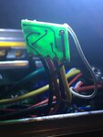
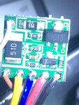
posting pics of light pcb
I got this controller (KT-6S5-C 2018-1-8) recently and I'm a bit scared of plugging lights without some testing before.
There are two outputs from controller (on board these are brown and yellow wire) It seems the yellow wire only goes through a 51kΩ smd resistor.
My battery is 36v and just measured the lights with a multimeter on 200mA.
Front light is continuous 95.6mA, rear light has a stop function which doubles LED's so peaks at 19mA +/- and stays continuous on regular one led at 5.6 mA.
I'm trying to figure this out before connecting it and burning the circuit
Would it be 100mA per output or for both?
posting pics of light pcb


