harryS
Well-Known Member
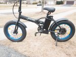
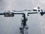
This is for the 36V Ecotric fat tire 20" folding ebike with the 810LED display,
Some more details about how I would change the 36V Ecotric controller with 810LED display to a KT controller. Looking at it from the objective of keeping the bike connectors the same, so the original controller could be replaced if desired.
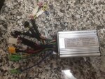
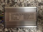
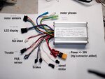
First, here is the Ecotric controller with most of the original connectors.
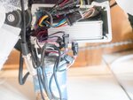
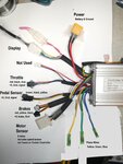
Next, here's a KT controller, very similar to the 20A sinewave controller I used. You would buy it with a compatible LCD display. While it has the same connector functions, most of them will use a different plug and the wire order and wire colors might change. WHile you can use any KT controller, you might want one that fits in the original compartment on the 20" fat tire folding ebike, That would be the smaller 17A and 20A KT controllers.
To keep the bike connectors untouched, the connectors on the KT controller are changed. I would recommend buying the next set of connectors. This would be
-one 6 pin JST connector (female),
-two 2 pin JST (male) connectors,
-optionally two 3 pin JST connector (male/female.)
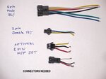
These are usually sold with both male/female pairs, with leads attached and in bundles of 5 or more. You can actually re-use the 3 pin connectors from the KT controller. Described below.
The project involves cutting off connectors from the KT controller, and splicing in different ones. It involves electrical skills like soldering and insulating wires. It requires electrical knowledge, as there is high power DC voltages in your ebike. Remove the battery before you do anything.
--------------------------------------------------------------------------------------------------------------------------------
1. POWER
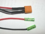
The power connections should be the same, but if you cannot figure out the red and black wires, this upgrade is not for you. Power is almost always a red and a black wire, sometimes with a connector supplied, like the yellow XT60, or often with bullet connectors. You may eveb get two bare wires.
2. DISPLAY
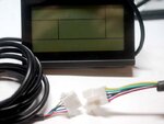
You will remove the 810LED and its cable. Your new LCD, if purchased with the KT display, will plug right in. It's the only 5 pin connector. I like the LCD3, shown here, but others like the color version poabb;y work nice too.
3.. MOTOR Phases
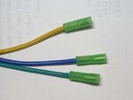
These are the thick green, blue, and yellow wires with bullet connectors. You'll find the same wires on both the Ecotric and KT controller, along with bullet connectors. Match the colors and connect.
4. MOTOR sensor
Cut this white 2x3 connector off the KT controller. Find your six pin JST connector.
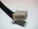
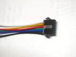
The colors on the JST do not matter, but the positions do.
blue - position 1 (Hall sensor)
green - position 2 (Hall sensor)
yellow - position 3 (Hall sensor)
black - position 4 (Ground)
white - position 5 (Speed sensor)
red - position 6 (5 volts)
Wire the six wires from the controller to the 6 pin JST using the above guide, per the figure below.. Note that the notch on the connector is facing upwards in this diagram,
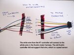
When this 6 pin JST is plugged into the matching connector on the Ecotric motor harness, you should see the colors on the original KT harness matching up to the wires from the motor. White to White, Red-Red, Black-Black, Yellow-Yellow, Green-Green, and Blue to Blue.
You might have noticed that this connector on the Ecotric controller did not use the white wire position. Happily for us, the Ecotric motor supports a speed sensor on the white wire, not used on the Ecotric controller but very important for the KT controller.
5. THROTTLE & PEDAL SENSOR
These are the two three wire plugs as shown on the above KT controller. I suggest cutting them off and re-using them as follows. The Ecotric bike harness uses a male plug for the throttle, and a female receptacle for the pedal sensor. The KT controller was different, so one can just switch the connectors and order the wires to match the signal position.
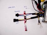
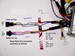
Some KT controller provide a third three pin connector,which is for an external speed sensor. It's not on the above photo. It's usually a white,red, black wire combination. Just ignore it if you have one.
6. BRAKES
The brake circuit in the Ecotric 20" folding fat bike is a switch that closes when the lever is pulled. The KT controller is designed for that, but it is also designed for three wire brakes that use power, so it has a a pair of three wire JST plugs. Cut these off. Carefully wrap the red wire because that is 5 volt power. Then connect the two remaining wires to the 2 pin JST plug you bought. There are two of these and they are in parallel.
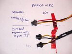
That's about what I remember. I actually did mine different. I kept the connectors on the KT controller the same, except for the brake connectors and motor connector, and I changed the PAS and throttle plugs on the bike harness to fit.
I won't discuss how to program the LCD. That depends on which unit you purchased.
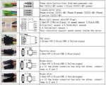
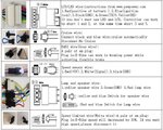
As a resource, here is a description of the KT connectors and also what Ecotric has released in their generic owners manual for the Ecotric wiring.

DISCLAIMER: This is not a tutorial. It is a discussion how I would modify a KT controller. I have not actually done the above because i chose to modify the Ecotric harness instead of the controller harness, so there may be items I did not consider. Not responsible for differences in wiring or wire colors made by either Ecotric or KT. I can only describe what I had.
Proceed at your own risk.


Some more details about how I would change the 36V Ecotric controller with 810LED display to a KT controller. Looking at it from the objective of keeping the bike connectors the same, so the original controller could be replaced if desired.
First, here is the Ecotric controller with most of the original connectors.

Next, here's a KT controller, very similar to the 20A sinewave controller I used. You would buy it with a compatible LCD display. While it has the same connector functions, most of them will use a different plug and the wire order and wire colors might change. WHile you can use any KT controller, you might want one that fits in the original compartment on the 20" fat tire folding ebike, That would be the smaller 17A and 20A KT controllers.

To keep the bike connectors untouched, the connectors on the KT controller are changed. I would recommend buying the next set of connectors. This would be
-one 6 pin JST connector (female),
-two 2 pin JST (male) connectors,
-optionally two 3 pin JST connector (male/female.)

These are usually sold with both male/female pairs, with leads attached and in bundles of 5 or more. You can actually re-use the 3 pin connectors from the KT controller. Described below.
The project involves cutting off connectors from the KT controller, and splicing in different ones. It involves electrical skills like soldering and insulating wires. It requires electrical knowledge, as there is high power DC voltages in your ebike. Remove the battery before you do anything.
--------------------------------------------------------------------------------------------------------------------------------
1. POWER
The power connections should be the same, but if you cannot figure out the red and black wires, this upgrade is not for you. Power is almost always a red and a black wire, sometimes with a connector supplied, like the yellow XT60, or often with bullet connectors. You may eveb get two bare wires.

2. DISPLAY
You will remove the 810LED and its cable. Your new LCD, if purchased with the KT display, will plug right in. It's the only 5 pin connector. I like the LCD3, shown here, but others like the color version poabb;y work nice too.

3.. MOTOR Phases
These are the thick green, blue, and yellow wires with bullet connectors. You'll find the same wires on both the Ecotric and KT controller, along with bullet connectors. Match the colors and connect.

4. MOTOR sensor
Cut this white 2x3 connector off the KT controller. Find your six pin JST connector.


The colors on the JST do not matter, but the positions do.
blue - position 1 (Hall sensor)
green - position 2 (Hall sensor)
yellow - position 3 (Hall sensor)
black - position 4 (Ground)
white - position 5 (Speed sensor)
red - position 6 (5 volts)
Wire the six wires from the controller to the 6 pin JST using the above guide, per the figure below.. Note that the notch on the connector is facing upwards in this diagram,

When this 6 pin JST is plugged into the matching connector on the Ecotric motor harness, you should see the colors on the original KT harness matching up to the wires from the motor. White to White, Red-Red, Black-Black, Yellow-Yellow, Green-Green, and Blue to Blue.
You might have noticed that this connector on the Ecotric controller did not use the white wire position. Happily for us, the Ecotric motor supports a speed sensor on the white wire, not used on the Ecotric controller but very important for the KT controller.
5. THROTTLE & PEDAL SENSOR
These are the two three wire plugs as shown on the above KT controller. I suggest cutting them off and re-using them as follows. The Ecotric bike harness uses a male plug for the throttle, and a female receptacle for the pedal sensor. The KT controller was different, so one can just switch the connectors and order the wires to match the signal position.


Some KT controller provide a third three pin connector,which is for an external speed sensor. It's not on the above photo. It's usually a white,red, black wire combination. Just ignore it if you have one.
6. BRAKES
The brake circuit in the Ecotric 20" folding fat bike is a switch that closes when the lever is pulled. The KT controller is designed for that, but it is also designed for three wire brakes that use power, so it has a a pair of three wire JST plugs. Cut these off. Carefully wrap the red wire because that is 5 volt power. Then connect the two remaining wires to the 2 pin JST plug you bought. There are two of these and they are in parallel.

That's about what I remember. I actually did mine different. I kept the connectors on the KT controller the same, except for the brake connectors and motor connector, and I changed the PAS and throttle plugs on the bike harness to fit.
I won't discuss how to program the LCD. That depends on which unit you purchased.
As a resource, here is a description of the KT connectors and also what Ecotric has released in their generic owners manual for the Ecotric wiring.


DISCLAIMER: This is not a tutorial. It is a discussion how I would modify a KT controller. I have not actually done the above because i chose to modify the Ecotric harness instead of the controller harness, so there may be items I did not consider. Not responsible for differences in wiring or wire colors made by either Ecotric or KT. I can only describe what I had.
Proceed at your own risk.
Last edited:

