Jaro No
New Member
- Region
- Europe
Hi,
I'm trying to repair a Darfon E4C0C battery used with a Shimano STEPS system and I'm looking for someone who has experience repairing or diagnosing these Darfon BMS boards.
Battery details:
Darfon E4C0C
36.3 V / 14 Ah / 508.2 Wh
10INR19/66-4
MFW: 0.0.007
GFW: 01.FF
The battery does not work in the bike and does not start charging with its original Darfon charger.
What I've checked so far:
Complete cell pack: ~39.5 V
All 10 series groups are very even, approximately 3.95 V each
No obviously weak or discharged group
Temperature sensor: ~9.25 kΩ at room temperature, dropping to about 7.7 kΩ when warmed, so the NTC appears to work
B+ to B−: 39.5 V
B+ to P−: 39.5 V
B− to P−: 0 V
B+ to P+: approximately 28.7 V
Voltage measured directly at P+ / P− is only around 2 V and unstable
The original Darfon charger is rated 42 V / 4 A. Its LED remains solid green both before and after connecting the battery. Charging never starts.
The battery's LED/display electronics are alive. Pressing the battery button shows the charge level (4 LEDs). Shortly afterwards LEDs 1, 3 and 5 illuminate briefly. According to the Darfon documentation this appears to be the normal shutdown indication rather than an error code.
Holding the button for several seconds gives the same result: charge LEDs appear, then go out, and LEDs 1/3/5 appear after releasing the button.
The same battery also does not power its original bicycle, so this isn't only a charger/adapter issue.
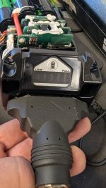
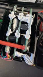
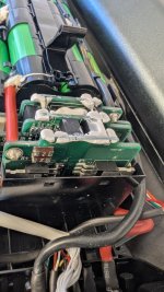
The BMS is the unusual multi-PCB Darfon design shown in the attached photos. There is an F1 fuse on the B+ board and several power semiconductor stages.
Has anyone repaired this exact E4C0C BMS or knows how its power/charge enable circuit works?
In particular I'm trying to determine:
What should cause P+ to be enabled?
Is there a known BMS lock/protection state that prevents both charging and discharge even with balanced cells?
Is there a documented reset/wake-up procedure?
Is communication with the bike/charger required before the BMS enables the power stage?
Has anyone identified the communication protocol or diagnostic interface on this BMS?
Are replacement E4C0C BMS boards available, or can the original board be repaired/reset?
I have the battery open and can take measurements with a multimeter, oscilloscope/logic analyser and CAN hardware if needed.
I would prefer to diagnose the original BMS rather than replace it with a generic BMS, because the battery needs to remain compatible with the Shimano system.
Any schematics, pinouts, service information or measurements from a working E4C0C would be very helpful.
Thanks.
I'm trying to repair a Darfon E4C0C battery used with a Shimano STEPS system and I'm looking for someone who has experience repairing or diagnosing these Darfon BMS boards.
Battery details:
Darfon E4C0C
36.3 V / 14 Ah / 508.2 Wh
10INR19/66-4
MFW: 0.0.007
GFW: 01.FF
The battery does not work in the bike and does not start charging with its original Darfon charger.
What I've checked so far:
Complete cell pack: ~39.5 V
All 10 series groups are very even, approximately 3.95 V each
No obviously weak or discharged group
Temperature sensor: ~9.25 kΩ at room temperature, dropping to about 7.7 kΩ when warmed, so the NTC appears to work
B+ to B−: 39.5 V
B+ to P−: 39.5 V
B− to P−: 0 V
B+ to P+: approximately 28.7 V
Voltage measured directly at P+ / P− is only around 2 V and unstable
The original Darfon charger is rated 42 V / 4 A. Its LED remains solid green both before and after connecting the battery. Charging never starts.
The battery's LED/display electronics are alive. Pressing the battery button shows the charge level (4 LEDs). Shortly afterwards LEDs 1, 3 and 5 illuminate briefly. According to the Darfon documentation this appears to be the normal shutdown indication rather than an error code.
Holding the button for several seconds gives the same result: charge LEDs appear, then go out, and LEDs 1/3/5 appear after releasing the button.
The same battery also does not power its original bicycle, so this isn't only a charger/adapter issue.
The BMS is the unusual multi-PCB Darfon design shown in the attached photos. There is an F1 fuse on the B+ board and several power semiconductor stages.
Has anyone repaired this exact E4C0C BMS or knows how its power/charge enable circuit works?
In particular I'm trying to determine:
What should cause P+ to be enabled?
Is there a known BMS lock/protection state that prevents both charging and discharge even with balanced cells?
Is there a documented reset/wake-up procedure?
Is communication with the bike/charger required before the BMS enables the power stage?
Has anyone identified the communication protocol or diagnostic interface on this BMS?
Are replacement E4C0C BMS boards available, or can the original board be repaired/reset?
I have the battery open and can take measurements with a multimeter, oscilloscope/logic analyser and CAN hardware if needed.
I would prefer to diagnose the original BMS rather than replace it with a generic BMS, because the battery needs to remain compatible with the Shimano system.
Any schematics, pinouts, service information or measurements from a working E4C0C would be very helpful.
Thanks.