walawn
Active Member
Ok, so as some of you who follow this forum may know, the first week I had my new Radrover I was an idiot. I went out for a multi-hour afternoon ride and didn't lock my battery onto the frame with the key. Of course it wasn't until the last few miles that I hit a bump that sent it flying off the bike at 20 mph only to hit the paved trail, bounce, and skid it's way to a stop. The battery looked like I put it into a giant food processor. Needless to say I was distraught at what just transpired and a little worried that I did some irrevocable damage to me $500 battery. I slid it back into the holder and the bike did get me home under full throttle. Please see my post on here for what I did to repair it that night (sanding down the damage and painting it with plastidip). Being the perfectionist I am, I wanted a new case. After waiting a week for the factory in China to ship it I had it in my hands (shipping cost more than the case!). Now it just so happens that I had just finished charging my battery when the new case arrived so I had no choice but to do the swap over with a fully charged (read here: 54.6 V) battery. There will always be some energy left in your battery, but it would have been safer to do the swap with a discharged battery. Now I am a certified motorcycle repair technician (15 years experience), but don't practice anymore so electrics are nothing new to me. I would advise you to wear gloves, eye protection, and remove the fuse. This post is only for informational purposes and I will not be responsible for any injury or property damage from following this guide. If you are in doubt, then don't do it!
Step by Step:
1. Remove the fuse. (this only protects the output side of the battery, charging side will be live (54.6 V)!
2. Remove the 6 screws holding the case together (5 will be long and 1 will be short.)
3. Slowly pull apart the halves of the case. Be careful of the handle/spring assembly at the top. Remember how it goes together.
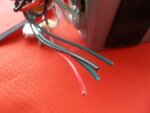
4. You will need to cut the 4 power switch wires (1 red, 1 black, 2 green) going from the battery to the silver/blue power button. Note: You will need to mark one of the green wires with a marker and remember it's position (I marked the green wire closest to black).
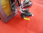
5. You will need to cut the 2 wires going to the charging port or unsolder them. Use caution! This connection is live. Note: Remember their orientation so you can reattach them correctly.
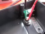
6. I soldered some extra wire onto the charging input (6-8 inches) just because I wanted more room to work. Insulate and isolate all connections. The positive and negative are VERY close together so BE CAREFUL (maybe a mm to spare).
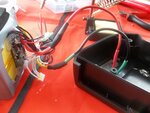
7. I then soldered the extra wire to the charging wires coming from the battery. Make strong connections and use heat shrink.
8. I removed the LED battery gauge display from the old case which saved me some time soldering.
9. You can just unplug the white USB connector and plug it into the new one. Also unscrew the fuse holder.
10. Place the main battery in the new case. Screw down the LED board. Plug in the USB connector.
11. Lightly place the output into the new case with the notch facing up. Do not tighten nut yet. Screw down the fuse holder.
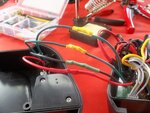
12. Place heat shrink on the 4 power wires. Solder the black power wire first. Then the green you marked. Then the other green. Lastly do the red. Check your connections and heat the shrink to finish the job.
13. Very carefully pack all your wiring in the front and place the two halves of the case together. You want to do slowly so you don't damage anything. The extra wire I installed made this a tight fit. Check that you have power (press button and then press gauge).
14. Once you have the halves together grab your handle/spring assembly. Lightly pull the halves apart and place the handle/rod in between with tension on the spring.Once installed, wiggle the halves back together.
15. Reinstall all bolts being careful to place the short one in its place. Tighten the nut on the output at the bottom. Check your voltage at the output with the button on. You should get a reading 45-55 V. You are done!
Picture explanations:
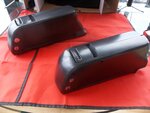
Old and New: New case in front (pristine condition w/ keys inside it) and old case in back (with scratches and a peeling plastidip finish)
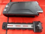
New with Holder: The new case on its side and the holder it came with. I will save it for a future project.
New Case: Once I got the new case open. This is the view that greeted me.
Cutting Old: I had to really work to get the old case apart, cutting where the seam is. As long as you don't paint your case, you can skip this step.
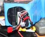
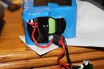
BMS Old: Some of you wanted to see the view inside of our OEM batteries. Here it is.
Inside Old: The padding and packaging of the cells likely saved it from damage during the fall.
Cut Power Wires: I tried to not cut any wires, but eventually had to. Here are the power wires going to the button.
Cut Charging Wires: I just wiggled them on the input until metal fatigue broke them off. Don't let them touch!
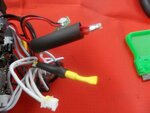
Protect Yourself: I put some heat shrink on one wire temporarily. I measured over 54 V with a multimeter once off.
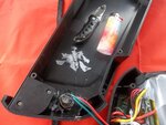
Power Switch Old: Here was my attempt to muscle out the power switch, which was glued down by the factory, with a hot knife. Fail.
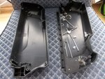
Old Halves: Finally got the old case off. Here are the two halves with hardware.
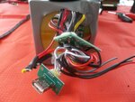
Gauge and USB: Here is the LED battery level gauge and USB port after removing them from the old case. I used the new USB since it was already bolted down. Simply unplug and replug.
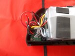
Pack in But Not Done: Here is the battery resting in one of the new case halves with the charging wires soldered. Notice the extra wire (red/black) which let me solder without going crazy.
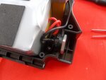
Orientate Input Correctly: Here I lightly placed the output plug with the notch facing up.
Finished Power Soldering: Here are my 4 power button wires soldered and heat shrunk.
Charging Leads Installed: Here I soldered extra wire onto the charging barrel plug connector. Very close tolerance. Easy to short.
Charging Leads Finished: Here is the finished job of connecting the extra wire I installed to the battery.
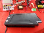
Finished Product: Here is the old battery in the new case!
It Even Works!: Power button lights up.
And It's Full!: Battery gauge works. Shows full. Checked voltage at output +/-. Voltage was 54+ volts.
Attachments
-
 Old and New.JPG681.3 KB · Views: 1,745
 -
 New with holder.JPG600.3 KB · Views: 2,192
 -
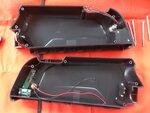 New Case.JPG590.9 KB · Views: 2,255
 -
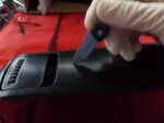 Cutting Old.JPG622.8 KB · Views: 1,600
 -
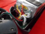 BMS Old.JPG613.7 KB · Views: 1,710
 -
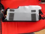 Inside Old.JPG615.6 KB · Views: 1,697
 -
 Cut Power Wires.JPG633.8 KB · Views: 1,558
 -
 Cut Charging Wires.JPG607.7 KB · Views: 1,521
 -
 Protect Yourself.JPG586.9 KB · Views: 1,531
 -
 Power Switch Old.JPG678.5 KB · Views: 1,826
 -
 Old Halves.JPG654.7 KB · Views: 1,645
 -
 Gauge & USB.JPG641.1 KB · Views: 1,640
 -
 Pack In But Not Done.JPG634.6 KB · Views: 1,577
 -
 Orientate Input Correctly.JPG633.8 KB · Views: 1,581
 -
 Finished Power Soldering.JPG615.7 KB · Views: 1,662
 -
 Charging Leads Installed.JPG617 KB · Views: 1,636
 -
 Charging Leads Finished.JPG588.6 KB · Views: 1,541
 -
 Finished Product.JPG591.9 KB · Views: 1,467
 -
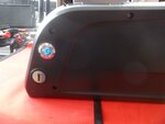 It even Works!.JPG614.6 KB · Views: 1,489
 -
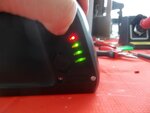 And It's Full!.JPG600 KB · Views: 1,516
