New Member Washington State

Wiley1

New Member
Region
USA
Hello all, I'm a New member and it was suggested that I introduce myself. So...


I live in Western Washington State, on a small island. I moved here 35 years ago, back when land on island was affordable by mere mortals. It took four years but I built my home myself out of pocket. I suspect I am older than most here, but while I may be old, I'm not dead yet. Bicycles have been a significant part of my interests and as I get older ebikes are becoming a viable option. I have toured on bicycles in Europe, spending Septembers for three years touring in France and Germany. In 2015 I met a French gentleman on Eurovelo 6 who had just received an ebike as a gift from his son. He was 80 and had for many summers toured Eurovelo 6 (also known as Loire a' Velo) and the new bike was a way of continuing his cycling. A seed was sown.


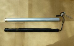
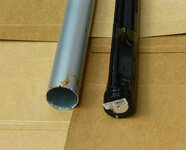
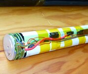
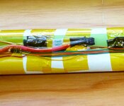
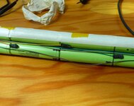
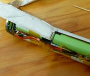
I recently acquired a Faraday Porteur S at a Goodwill for a pittance. It was too good a deal to pass up...the tires alone were worth more than they were asking for the ebike. Of course there are issues...otherwise it wouldn't have been there. It has a dead battery and my search for information led me to this forum via postings from a member...Darthracing. His response from members here suggested that perhaps this would be a good source for advice and suggestions concerning the Faraday as well as other ebike options. Bests, Wiley1
 
Welcome. I live in SW WA but have camped and ridden on Lopez with my wife, also ridden on Whidbey. That was years ago, maybe I'll get around to do it again sometime.
I watched Court's review of your bike, nice looking bike with torque sensor and IGH - great find if you're up to a project. I would have bought it too. Just reading Darthracing's posts and video clip I'll throw out a couple things. From his posts his isn't working correctly. The motor shouldn't run on without continued pedaling, I wonder if he ever resolved that but didn't see any follow up posts indicating that he got it running correctly. Regarding the battery at 43v nominal - I have a 48v 5ah power tool battery and found that they aren't rated like regular ebike batteries. Instead the rated voltage, 48v in my case, is the maximum fully charged voltage, while the nominal is 43v - like the Faraday. You can remove the old battery and check if the battery terminals are simple +/- connections or if there is a data port that communicates with the controller to allow for proper function of the motor. I know Darthracing hooked up a generic battery but he didn't give details regarding the connections. If there is a data wire connection maybe that is the reason his didn't work correctly (including why his battery charge indicator didn't light up). Or if you're lucky maybe his didn't work correctly because he was over volting the controller with his after market 48v battery which fully charged would be 54v. I sort of expect that it is more the need for a data connection between the battery and the controller. Try not to destroy your old battery and BMS like he did, maybe there is a chance that the cells can be replaced.
Thank you for the kind welcome!
Regarding the Faraday Porteur S battery, I have removed the battery from the ebike and carefully disassembled the internal shrink wrapped package of battery and BMS from the aluminum tube in which it was housed. It looks undamaged. My "cunning plan" (with apologies to Baldric of Black Adder fame) was to carefully expose the battery and all the wires. I'm expecting several batteries in series with those series wired in parallel to create the 43 volts. Making note (and marking the leads both for positive and for pairs) remove the BMS wires from the cells or cell sets and remove the old cells completely from the old battery package. My understanding is the purpose of the BMS is to equalize the batteries to near the same voltage (each battery or 'set" of batteries). Now this is the hopefully cunning part: I will attach all the positive leads of the BMS to the positive end of an artificial/fake battery and likewise attach the negative leads to the negative end of the fake battery. The fake battery will consist of 2032 cells, each at a nominal 3 volt charge stacked as needed to create the correct voltage. The number of 2032 cells equaling the number of 18650 batteries since 3 volts is within operating voltage for the 18650 cells. Since the voltage will be the same for all my expectation (and hope) is the controller will be fooled into thinking all is well. The external new battery will attach to where the final output from the original battery connected. The new battery having its own BMS and charged externally should have little effect on the BMS of the original battery.
So knowledgeable people: what am I missing? will this work or not?
Thank you in advance!
Wiley
 

Attachments

  • Cell package removed from tube.jpg
    Cell package removed from tube.jpg
    223.2 KB · Views: 13
  • Battery end cap along side battery tube.jpg
    Battery end cap along side battery tube.jpg
    286.7 KB · Views: 15
Last edited:
Thank you for the welcome JGcycle and Codydog.

EMGX, there are two cable connections to/from the battery. One is a three pin and is the one carrying the red and black power wires (they are larger wires) if the third pin is even connected/used I do not yet know. The second cable, which I suppose is data, is a four pin with small pins. That cable runs up to the controller. So there are three cables that run up to the controller: two from the battery and one from the torque sensor bottom bracket. Following what cable goes where is complicated by the manner in which the wires are run up and around the seat post. The tube in which the seat post actually is held is inside an outer tube. It is eccentric in the tube and the wires were fed thru the space created by the eccentricity...and that's not much space. The cables running up are all in black sheaths but those sheaths are removed (beyond were one can see even with an endoscope) and the wires separated and spread out to run thru the tight space. They come back into sight as individual color coded wires in the space before they enter the sealed controller. They are color coded but which is what and who goes where is hard to determine. There is no coupling before the modular controller...so replacing the controller would not be an easy task. I have not figured out the actual path of the power cable from the controller to the motor.

Thinking over the situation with Darthracing's motor continuing to run after the pedal stopped turning...the torque sensing cable runs up to the control box at the top. I think it is possible that his problem with this lies with the torque sensor in the bottom bracket...it sends a signal to turn on but fails to send a signal to turn off. Worse case the controller gets a signal to turn off the motor from the torque sensor but doesn't.

It would be nice to have a schematic of the electrical but the designer, previous owner and current owner have not made any of that sort of info public. Not that they have to, however, they have even blurred out a simple diagram online of where the wires run. The first generation Porteur had the batteries in the two top tubes. This generation moved the batteries to the down tube. Several questions arise as to location of the original BMS as well as any changes in its capabilities for this generation...did they include a high or low temperature cut off?

Off to doctor's visit today (one of the joys (not!) of advanced years). Tomorrow I start dissection of the battery package.
Bests,
Wiley1
 
Update on battery: I stripped the shrink wrap off and then removed several strips of white tape. I suspect the white tape was more to tie everything together but it may have been a bit for dielectric protection as well. The batteries are Panasonic and are dated 2012....age might be part of the reason the battery no longer worked. The ebike looks like it was used and enjoyed as opposed to being a garage queen. Then too I suspect a bit of corrosion I found may have been the culprit. There is one photo I would appreciate peoples input on. It appears to be a fuse. It is at the end of a short heavier gauge red wire and appears to be where the actual positive end of the battery connects to the BMS. I included a photo of that wire, there are also some photos of the corrosion as well as others of the BMS wires that some may find interesting.
Bests, Wiley1
 

Attachments

  • Shrink wrape removed note red wire..jpg
    Shrink wrape removed note red wire..jpg
    384 KB · Views: 25
  • Closeup of red wire and fuse.jpg
    Closeup of red wire and fuse.jpg
    203.6 KB · Views: 25
  • BMS wires panasonic cell dated 2012.jpg
    BMS wires panasonic cell dated 2012.jpg
    393.8 KB · Views: 25
  • Note corrosion on tape.jpg
    Note corrosion on tape.jpg
    302.1 KB · Views: 24
Back