You are using an out of date browser. It may not display this or other websites correctly.
You should upgrade or use an alternative browser.
You should upgrade or use an alternative browser.
Wire Organizing- What Do You Use?
- Thread starter Ken Shopken
- Start date


Gionnirocket
Well-Known Unidentified Member
- Region
- USA
- City
- Y. O.
But who here is making a Western Union splice... and then to the NASA STANDARD?The test splices never failed at the splice (instead breaking outside of the splice area), leaving NASA to conclude that "the solder connection at the splice was as strong or stronger than the un-spliced wires".
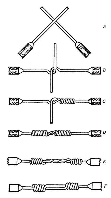
Western Union splice - Wikipedia
en.wikipedia.org
The NASA tests included soldering, and were performed to an organizational standard operating procedure (NASA-STD-8739.3) for a solder termination, which includes a number of specific requirements, including "proper insulation spacing"; tight wrapping; trimming of wire ends to prevent protrusions through the solder; and over-sleeving with a transparent or translucent heat shrink seal to cover the completed splice and all exposed metal.[7]
The article is about the strength of a Western Union splice, not solder and only states that solder didn't make it weaker. And the testing was for tensile strength such as for a wire going from pole to pole where a Western Union splice was used.
It's also for solid wire, not stranded.
It's the small details Norton
Last edited:
stompandgo
Well-Known Member
- Region
- USA
Heating the wire weakens the copper annealing on both sides of the joint. Soldering creates a stress riser where the solder ends and the clean wire begins. Solder joints should always be supported structurally, with wrap, ties, clamps and the like.
spokewrench
Well-Known Member
- Region
- USA
@PedalUma : "When I was about nine, my dad told me to never rely on a soldered joint for mechanical strength." A soldered joint can be reliable.The article is about the strength of a Western Union splice, not solder and only states that solder didn't make it weaker. And the testing was for tensile strength such as for a wire going from pole to pole where a Western Union splice was used.
It's also for solid wire, not stranded.
My house was wired in 1926. The Western Union splices are still fine. The electrician was killed shortly afterward, wiring lights at a ball park. I know he wired my house right because there are no twisted (AKA rattail or pigtail) splices. Some electricians used to twist and tape, but that's not allowed in household wiring because even solder doesn't make it reliable.
That's why I don't like wire nuts over twisted splices. If a nut can solidly clamp conductors and jackets, it's great. More than once, I've used wire nuts to repair headphone cables. The stranded conductors were so delicate that they included polyester strands for tensile strength. I'd tin them for stiffness. A properly applied wire nut would clamp bare conductors together and clamp them where they were jacketed. I never had one pull apart.
I could have used wire nuts to splice a brake sensor cable, but then I would have had to keep the nuts from flopping. In that case, I used solder and marine heat shrink.


RunForTheHills
Well-Known Member
- Region
- USA
My nuts always shrink and never flop in the cold though...but then I would have had to keep the nuts from flopping. In that case, I used solder and marine heat shrink.
Gionnirocket
Well-Known Unidentified Member
- Region
- USA
- City
- Y. O.
There is practically no reasons to use a Western Union splice in a home. The only time I ever seen it in a home was with knob and tube wiring which should be replaced no matter how well it was done.

PedalUma
Well-Known Member
- Region
- USA
- City
- Petaluma, CA
An interesting one is coming in today or tomorrow. The owner has already made a deposit. It is a titanium road bike, handmade in Ohio twenty-years-ago. It has couplings on the toptube and downtube. When you take the wheels off and open the couplings, and turn the bar, the whole bike fits into a padded suitcase that is not much bigger than the wheels. The rear brake and derailleur cables also have couplings. My design of wire management has to allow for the bike to come apart and get put back together. Before I accepted the job I carefully inspected the chainstays. They are strong enough to take the torque. During our initial phone call I was tentative/hesitant. Years ago there was a lightweight road bike that when power was applied it would flex the chainstays and drop the rear wheel.
spokewrench
Well-Known Member
- Region
- USA
You must be thinking of Thomas B. Doolittle: 1839 to 1921. Telephone wire used to be iron. Copper had 90% less resistance, but each step of drawing it into wire made it harder. That increased tensile strength but also made it increasingly brittle. By the time they had the gauge they wanted, it was fragile. Resistance would also increase due to the crystals broken by the mechanical working.Heating the wire weakens the copper annealing on both sides of the joint. Soldering creates a stress riser where the solder ends and the clean wire begins. Solder joints should always be supported structurally, with wrap, ties, clamps and the like.
Heating copper to a temperature between 700 and 1200 F anneals it. Crystals repair themselves for better conductivity. It becomes more ductile. Most copper wire sold is annealed. By annealing between drawing steps, Doolittle invented hard-drawn copper wire, with twice the tensile strength of annealed copper but not brittle.
In 1906, a phone company in Iowa began soldering Western Union splices. Soldering swept the industry because it made phone lines quieter. I suppose they heated the splice with a torch and then pressed solder to it. The temperature may have been hot enough to anneal the wire, hardened by bending it into the splice. Annealing can heal tiny cracks that cause electrical noise.
Last edited:
PedalUma
Well-Known Member
- Region
- USA
- City
- Petaluma, CA
Off topic; forgive me. I am getting excited about the Ti bike. It will be in my shop in less that two hours. Today I will prep the motor to paint it with titanium look automotive engine enamel. It is getting a bunch of accessories and upgrades. The final one arrived today; polished square taper cranks. I will be soldering inside the motor's housing. It will have one connector to the display that I will move to the downtube joint. If rosen heats it makes smoke, so if you solder the negative and positive, you have just smoked two joints.
Funny thing about the Ti bike is that you would need a lock five-times heavier than the bike.
Funny thing about the Ti bike is that you would need a lock five-times heavier than the bike.
Last edited:
thank you so much for your suggestionTrue. Eleven years ago, my ebike kits had four cables that had to be routed to the handlebars, a fifth to the pedal sensor and then the motor harness. All were too long, of course. The controller was a big box with a rats nest of JST connectors, I used to hang the controllers on the downtube. Put all the cables in 1/2" automotive sheathing,
Then controllers were available with molded connectors and 4n1 handlebar harnesses, plus plastic boxes, Cables were fewer. I started using the spiral wrap to tie the 4n1 harness to a shifter or brake cable, Also shortened then when I could, I had one bike that routed the brake and shifter thru the frame. I ran the handlebar harness thru it, and it looked clean,
I will shorten cables. A lifetime of soldering experience. Shortening the motor cable is not advised, but I did it. I would use DIY solder ferrules for the heavier phase wires, but worry about strain relief, Best way to do that is buy a long 9 pin motor extension, cut it to length and solder the cut wires inside the controller, It's an easy solder joint, no strain/cracking issues, and protected from water.
PCeBiker
No-Hands No-Pedaling No-Credentials
- Region
- Canada
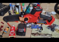
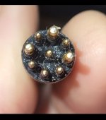
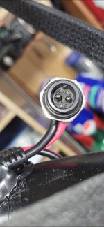
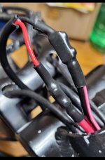
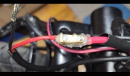
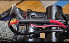
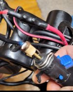
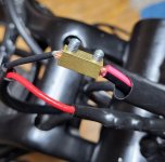
Waterproof Double Butted Power Cables for the New Motor,..
Each wire under two screws in a Butt Connector,..
Double walled heat shrink tube, over top of Silicone Dielectric Grease
No air in the Joint.
No oxidation.
Each wire under two screws in a Butt Connector,..
Double walled heat shrink tube, over top of Silicone Dielectric Grease
No air in the Joint.
No oxidation.
Attachments
-
 Screenshot_20260429_135523_Gallery.jpg264.4 KB · Views: 78
 -
 Screenshot_20260429_135906_Gallery.jpg138.5 KB · Views: 83
 -
 Screenshot_20260429_135912_Gallery.jpg137.3 KB · Views: 89
 -
 Screenshot_20260429_135833_Gallery.jpg229.2 KB · Views: 80
 -
 Screenshot_20260429_135859_Gallery.jpg115.7 KB · Views: 80
 -
 Screenshot_20260429_135855_Gallery.jpg186.7 KB · Views: 60
 -
 Screenshot_20260429_135846_Gallery.jpg213.1 KB · Views: 81
 -
 Screenshot_20260429_135839_Gallery.jpg140.8 KB · Views: 74
 -
 Screenshot_20260429_135504_Gallery.jpg245 KB · Views: 83
Similar threads
- Replies
- 1
- Views
- 8K