Trikke T12 electrolizing

NormL1

Member
Not surprising, I didn't see a Trikke forum, so, mods place where you feel it is best. I have a Trikke T12 and at my weight, I can't get it to move more than 30 feet and forget it at the slightest incline. Hand it over to small person and off they go ... @#*&@!

I am planning on the 1000 watt 48 volt Magic Pie external (Link Removed - No Longer Exists) with their hard case battery.
(Link Removed - No Longer Exists) (Link Removed - No Longer Exists)

Here is my biker's question. I known that I have to cut and re-weld the front fork to get the 16" Magic Pie in where the 12" stock wheel was. Is it possible that this is a standard fitment and I could find a fork already to size? The reason I ask is, that it isn't just moving the forks down it is widening them as well. Currently they are 90mm inside face to inside face (MP=100mm). I am also going to spin the fork around as they fitted it backwards for better carving
(Link Removed - No Longer Exists) (Link Removed - No Longer Exists) (Link Removed - No Longer Exists)

I was originally looking for a system that would not have resistance to carving, but, I couldn't find one that would fit and was even close to 1000 watts. The Magic Pie will resist me carving, but, this is going to be a pit bike so who cares. I will 3D print the mounts and clips as needed. I still need to figure out what else I need as I do find their website kind of confusing at first look. I think I need to add their Cycle Analyst to this too as I don't want to have to use my phone.
 
Not surprising, I didn't see a Trikke forum, so, mods place where you feel it is best. I have a Trikke T12 and at my weight, I can't get it to move more than 30 feet and forget it at the slightest incline. Hand it over to small person and off they go ... @#*&@!

I am planning on the 1000 watt 48 volt Magic Pie external (Link Removed - No Longer Exists) with their hard case battery.
(Link Removed - No Longer Exists) (Link Removed - No Longer Exists)

Here is my biker's question. I known that I have to cut and re-weld the front fork to get the 16" Magic Pie in where the 12" stock wheel was. Is it possible that this is a standard fitment and I could find a fork already to size? The reason I ask is, that it isn't just moving the forks down it is widening them as well. Currently they are 90mm inside face to inside face (MP=100mm). I am also going to spin the fork around as they fitted it backwards for better carving

I was originally looking for a system that would not have resistance to carving, but, I couldn't find one that would fit and was even close to 1000 watts. The Magic Pie will resist me carving, but, this is going to be a pit bike so who cares. I will 3D print the mounts and clips as needed. I still need to figure out what else I need as I do find their website kind of confusing at first look. I think I need to add their Cycle Analyst to this too as I don't want to have to use my phone.

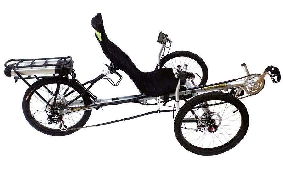
There are some wonderful Trikes you could try right now.


http://www.crazylennysebikes.com
5136.jpg


Also, HP Velotechnik makes high-quality trikes
https://electricbikereview.com/hp-velotechnik/scorpion-fs-26-s-pedelec/

May be we can share this here. Izip USA (Accell) is coming up with mid-drive Trike!
A lot of the existing trikes have front wheel drive and makes it difficult to get traction. A mid-drive on a trike would be ideal to make use of the gearing and all three wheels.
 
I wonder if the shareroller would work on this. It would be a lot simpler than rebuilding the forks, but it is now not going to be available until August:

https://www.indiegogo.com/projects/shareroller-add-on-e-power-for-bikes-scooters#/

That is interesting. I am a little skeptical of the one size fits all really well pitch, but, it is worth a hard look.

There are some wonderful Trikes you could try right now.

http://www.crazylennysebikes.com
5136.jpg


Also, HP Velotechnik makes high-quality trikes
https://electricbikereview.com/hp-velotechnik/scorpion-fs-26-s-pedelec/

May be we can share this here. Izip USA (Accell) is coming up with mid-drive Trike!
A lot of the existing trikes have front wheel drive and makes it difficult to get traction. A mid-drive on a trike would be ideal to make use of the gearing and all three wheels.

I want my standup over powered idiocy for myself (I have an Izip Express), but, my wife is talking about a more normal trike for herself. I will definitely be interested in what Izip has coming up
 
@NormL1 , why don't you take a look at one of the electrified Trikkes, the PonE models? they boogie pretty good down the road, up to 20mph! They have both a 48V and 36V lithium powered versions so you don't have to mess with the cambering system that allows the rider to rock the trikke from side to side to move forward. And if you don't like the front body panels, they're removeable.

Pon-e-48v.jpg
 
Ann, I am a very big guy and the T12 is more size appropriate. Think football lineman size. That particular PonE was designed on the T8 frame, which means 8" rear tires. More to the point it is only 350 watts and I wonder if I can climb inclines with it. I do thank you for the thought, but, the PonE isn't clicking the boxes like the 1000w T12 does. This will not be an exercise in practicality, it is a pit bike which is practical idiocy by very nature. I didn't think of it, these guys have already done it and it is shown in the start of this vid (First 40 secs)
It does appear that they cut their fork and then chromed it instead of match painting
 
Thanks for the vid. I have the same Trikke T 12, in the same color . That shop is way cool ! Love my Trikke , really good workout . I'm covered head to toe when I ride with protective gear , even hip and tail pads. Those things are well made, aircraft aluminum, beautiful welds. Found some great elbow and knee pads at a skate board shop. Have fun with your build,
 
Last edited:
David, I so wanted it to work for me, but, I just can't get it to move under my power. Even my thirty foot trips showed me how much fun it would be and the workout you describe.

I did take a long look at the Shareroller and it is a great idea, but, you can't buy in now and everything is closed. Way too glandular for waiting myself, I am pushing forward. I took a look at Mxus, but, they can't be effective with the tiny wheel right now, but, 3000watts did get my attention. So buy the MP and size the fork is the next step
 
My Magic Pie should be here later this week, so, I am getting ready for the fork re-design. Hoping there are some people with a mechanical engineering background. I laser scanned the Trikke to determine what angles it was designed with in mind.
(Link Removed - No Longer Exists) (Link Removed - No Longer Exists)

I then dropped a plane through the asbuilt center of the Trikke
(Link Removed - No Longer Exists)

I come up with the rake at the front of the Trikke being 26.87° off of ground perpendicular and a 3.51" drop to wheel center from the main upright centerline. I also found the the two rear wheels toe out about 0.3°, which I thought would be more. The wheel center is 1.52" perpendicular to the main tube axis.

As I place the much larger wheel on it, the angle of 26.87° is going to get larger, by a lot. I would still like the carving feature to work after I am done, so, what am I trying to maintain? I do realize that switching the orientation to backwards would make it a better powered scooter, but, I am figuring the wheel is set inward for carving

The dimension that makes sense for me to maintain is the perpendicular to the steering axis to the center of front tire patch on the ground. I just measured it at 4.19 inches
 
Last edited:
More silliness.... I still think that the offset from the steering axis to the center of tire patch is the important one. I modeled an inflated tire on a quick model of a Magic Pie 4 and added that to the model of the tubes and floor from the laser scan. I come up with the entire Trikke having to pitch backwards 3.6° which is not as much as I had thought it would be. I will also need to make the axle center closer to the steering axis than stock by about 1.1". This was done using a measured 1.26 foot diameter of the tire'ed Pie, which was a Kenda Kwest 16x1.50 100 psi tire. This tire does appear to be a low profile as the overall diameter is not really close to 16", so, I am assuming that bikes measure tires differently than cars do. I also find the center of Magic Pie wheel to be a 8.15mm offset from the center of mount for the 100mm mount to mount the wheel I have
(Link Removed - No Longer Exists)


I have been thinking this entire time that I was going to machine another fork, but, I took it apart and it is beautiful workable aluminum. So the dimensions for anyone following, move the hole down tube 1.82 inches, inward to the center of the tube 1.07 inches and move the left fork outward 10mm. This will place the wheel 1.8mm off center, but, I have serious doubts if that will be noticeable. Of course gusset the hell out of it including filling the inside
(Link Removed - No Longer Exists)


Of course this is based upon placing the center of tire patch at the same perpendicular distance from the center of shaft. I have had a mechanical engineer tell me that would be correct, but, neither he nor I have any experience with bicycle geometry

(looking for an answer I have posted this on one other forum)
 
I wonder if the shareroller would work on this. It would be a lot simpler than rebuilding the forks, but it is now not going to be available until August:

https://www.indiegogo.com/projects/shareroller-add-on-e-power-for-bikes-scooters#/

Yes, Shareroller would work. There would be some design issues though. The portion of the shaft that pivots isn't very tall (2-1/8") and the Shareroller has to pivot with the tire to function. You would end up printing your own attachment for the Shareroller, but, I see no reason why it couldn't be done. The torque would go through the tire to the contact patch. if I am understanding the mechanics well enough, so, I believe that you would end up structurally strengthening the fork regardless. With such a short attachment length, you would also have to strap to the axle center line as well.
 
More silliness.... I still think that the offset from the steering axis to the center of tire patch is the important one. I modeled an inflated tire on a quick model of a Magic Pie 4 and added that to the model of the tubes and floor from the laser scan. I come up with the entire Trikke having to pitch backwards 3.6° which is not as much as I had thought it would be. I will also need to make the axle center closer to the steering axis than stock by about 1.1". This was done using a measured 1.26 foot diameter of the tire'ed Pie, which was a Kenda Kwest 16x1.50 100 psi tire. This tire does appear to be a low profile as the overall diameter is not really close to 16", so, I am assuming that bikes measure tires differently than cars do. I also find the center of Magic Pie wheel to be a 8.15mm offset from the center of mount for the 100mm mount to mount the wheel I have
(Link Removed - No Longer Exists)


I have been thinking this entire time that I was going to machine another fork, but, I took it apart and it is beautiful workable aluminum. So the dimensions for anyone following, move the hole down tube 1.82 inches, inward to the center of the tube 1.07 inches and move the left fork outward 10mm. This will place the wheel 1.8mm off center, but, I have serious doubts if that will be noticeable. Of course gusset the hell out of it including filling the inside
(Link Removed - No Longer Exists)


Of course this is based upon placing the center of tire patch at the same perpendicular distance from the center of shaft. I have had a mechanical engineer tell me that would be correct, but, neither he nor I have any experience with bicycle geometry

(looking for an answer I have posted this on one other forum)

3DS-Max for the win!
Cool stuff, Norm.
 
Thanks Ravi, my big fear is that I need to add the length of the tire patch into the calculations as that does deliver leverage. A 12" tire does have less leverage than a 16" is what I am saying, but, since the leverage is more or less linear with the basic line of travel I am ignoring it at the moment (more because I don't know how to factor it in). My assumption is that the slight toe out of the rear tires, combined with the extreme camber they possess, creates leverage ahead of the center of front tire patch. This is why I am trying to maintain to offset distance from the main rotational axis. I could certainly be wrong, but, every design aspect I have thought about circles me back to this analysis. The part I know I am missing in this analysis is how to factor mass. Less massive people seam to have much more effective leverage than more massive people from just an observation standpoint. Intuitively this is telling me that more mass means more outward force to swing around the axis, which is maybe coming too quickly for the stock offset to axis and that I should actually make it small than I already am. In other words the more massive you are the shorter the distance wheel center to axis should be. I am maintaining for now the distance of 4.19", but, maybe I should cut that in half to 2.1" as I am at least twice the mass of the average. If I flip my 0.45" offset around the other way, the center line offset becomes 3.2", humm. OK, that is my first sips of coffee rambling Friday morning thought ...
 
Last edited:
I am bored waiting for the fabrication of the new fork, so, I 3D printed some brackets to hold on the battery plates. These are for the plates that Golden Motors uses to slide on their 48 volt 10 amp/hr packs. Notice how I made it for a pack on both sides?, that is the confidence that I have in one pack being enough for my weight. I glue an inner tube on the face of the mount so that it doesn't scratch and it has a rubber to painted metal seat. After they are zip tied on, they do not move, laterally or longitudinally. I always end up gluing my fingers together, it is never a pretty sight. I also printed a 2 mm bushing to go over the stub on the bottom of the steering shaft for the new fork to clamp onto.
(Link Removed - No Longer Exists)
 
I got the fork back from the machinists and they did a great job. Even made a cool little notch for the air nipple. The didn't understand my sketch and got the offset about twice what I requested from the center line of shaft or1.1 inches not 0.45 inches. After riding it, it doesn't matter, .. the last thing you are going to be thinking about is carving with any of your power on this. I did go the Luna Cycle route for a 52v battery.

(Link Removed - No Longer Exists) (Link Removed - No Longer Exists)

(Link Removed - No Longer Exists)

I cheese balled the wiring for now as I want to know if I am adding more or changing anything first. It is a front wheel drive burn off machine. 20 foot mark in the garage now and it was a little wet on the test drive so every time I asked for more power in a corner, .... massive understeer.

Magic Pie's are apparently limited to 380 rpm by their software, so, that equates to 17 mph with the tire I selected. Zero doubt I got there, doing a burnoff most of the way. I will have to research how to get more rpm and more speed. Your hill climbing limitation is how far you can lean forward and transfer weight.

I did make the battery mounts so I could place a second battery on them, I don't see the need as traction is the issue
 
That they are! This is just stupid fun now, which is what I wanted. If you enjoy yours as the cambering machine that they are, I do not suggest electrolizing it as it has lost that. It is more of a riding challenge now than exercise with the lack of traction and the huge understeer under power. I need to ride it more, but, I could see making the back brakes operate off of one lever and adding a front one.
 
Back