notcynical
New Member
- Region
- Canada
Hi,
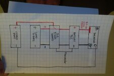
New member here and really appreciate the forums. I'm trying to rebuild an older 36V Bionx battery with a 5.2 board and wanted to add a proper BMS balancer since the original doesn't have that function. No problem building a 10s battery and wiring the balancer to it, but now I'm at the point of having reconnected to the Bionx board and need some help. I tried to follow a Dr Battery youtube video but he goes too fast at the important spots and doesn't properly show and explain his work so this is the configuration I think he did, but not 100% sure. When I tested this version with the pack I built, the charger went into charging mode and when I hooked up the battery to the bionx dock it powered up the g2 console and functioned properly. I'm just hoping there's a few battery experts on here who can tell me if I've done this BMS addition right or If I've created a potential fire hazard.

New member here and really appreciate the forums. I'm trying to rebuild an older 36V Bionx battery with a 5.2 board and wanted to add a proper BMS balancer since the original doesn't have that function. No problem building a 10s battery and wiring the balancer to it, but now I'm at the point of having reconnected to the Bionx board and need some help. I tried to follow a Dr Battery youtube video but he goes too fast at the important spots and doesn't properly show and explain his work so this is the configuration I think he did, but not 100% sure. When I tested this version with the pack I built, the charger went into charging mode and when I hooked up the battery to the bionx dock it powered up the g2 console and functioned properly. I'm just hoping there's a few battery experts on here who can tell me if I've done this BMS addition right or If I've created a potential fire hazard.


