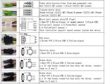
It looks like this in reality. And the Ecotric diagram is wrong. There's no white wire going into the 1x6 connector, because that controller does not support a speed sensor. However, there will be a white wire in the motor cable.
View attachment 42104
When you see it, it would make no sense to take the thin wires from 1x6 connector and mix them with the thicker phase wires just because they gave the same label assigned in a wiring diagram.
The Ecotric uses the 9 pin motor connector, and pretty much all the guys that use this connector use the standard wiring colors.
Radmotors, as far as I know, uses a nine pin connector, but they flipped it around so that the larger diamtere female side is on the motor, so it won't go thru the 12mm axle nut, THey may have even changed colors.
SInce I like to use connectors, this is a prototype of what could be used to go from the KT plug to the existing Ecotric plug. The KT controller has the white wire for the speed sensor built in, as does the cable on the Ecotric motor. I didn't do my actual swap this way, I had a spare white connector that I spliced to the Ecotric harness, but having an adapter would make it easy to go back. Similar adapters could be made for throttle/PAS.
View attachment 42105
Gotta go turn over the bird in the oven. Have a happy holiday!