Diy ebike issues

EbikeNooby

New Member
Region
USA
I recently acquired a DIY ebike. The person I bought it from demoed it for me and it seems simple enough how to charge the battery and how to connect the battery to the cable that powers the motor control etc. However, after I took it home and put it on the charger, for some ungodly reason I cannot figure out how to connect the power cable from the battery to the cable that connects to the motor control. It has two different kinds of connectors. I tried to get in touch with the person I bought the bike from, but just to keep it simple, they weren't providing any help. Any thoughts about what I can or should do here?

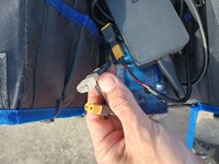
Below I have a picture of the two different connectors which you should be able to see fairly clearly. You can also see the battery charger in the top right. I can provide other pictures if needed. Basically the power cable from the battery has a black and a red wire. The wires going back to the motor control are white, black, and blue. I believe the blue is supposed to be the phase control.
 

Attachments

  • IMG_20231112_092617548_HDR.jpg
    IMG_20231112_092617548_HDR.jpg
    531.1 KB · Views: 129
The yellow connector in your hand, if it runs to the controller, replaces the charge connector from the charger to the battery.
The white one, I don't know. An unused stop connector to the brake handle? An unused PAS pickup (senses magnet wheel on the pedal shaft) connector?
 
That yellow plug in your hand is a female XT90 and as noted above, it is usually a connection to your controller. In fact, if I look into the picture background, I see an XT60 connector with a male XT90 adapter attached to it, and it doesn't look like anything is attached to that XT90 end, so the yellow plug in your hand is I think a match to the one in the background. And since that background cable is nothing more than a red and black wire, I'm thinking that red/black goes to the battery on its other side?

The white connector at least superficially resembles an XT90 male but not even junky clone XT90's use translucent white plastic. Seeing that worries me when thinking about the quality of work that went into this bike.

Typically - and especially on DIY builds - the battery's CHARGE (input) cable goes to an XT60 - a female XT60 to prevent shorting the two terminals. There is typically a second cable coming out of the battery that runs the bigger XT90, and that is the OUTPUT cable that goes to the controller. I would be a little worried that you are connecting a charge cable to your controller output via that XT60-XT90 adapter we are seeing. It would work, because electricity flows freely in both directions, but it would bypass some REALLY important safety features.

My concern is the seller half-assed the build and you are now facing the potential consequences.

It would be really, really helpful to see the rest of the wires and their start/finish sides.
 
Is that a charger in the picture, or is it the motor controller? A couple of good pics showing the power wires to the controller, and the cables coming out of the batter, please. The forum will fix you up. Hopefully the DIY guy didn't do something stupid.
 
The yellow connector in your hand, if it runs to the controller, replaces the charge connector from the charger to the battery.
The white one, I don't know. An unused stop connector to the brake handle? An unused PAS pickup (senses magnet wheel on the pedal shaft) connector?
I'm sorry if this is confusing. The white connector goes to the controller. The yellow connector goes to the battery.
 
That yellow plug in your hand is a female XT90 and as noted above, it is usually a connection to your controller. In fact, if I look into the picture background, I see an XT60 connector with a male XT90 adapter attached to it, and it doesn't look like anything is attached to that XT90 end, so the yellow plug in your hand is I think a match to the one in the background. And since that background cable is nothing more than a red and black wire, I'm thinking that red/black goes to the battery on its other side?

The white connector at least superficially resembles an XT90 male but not even junky clone XT90's use translucent white plastic. Seeing that worries me when thinking about the quality of work that went into this bike.

Typically - and especially on DIY builds - the battery's CHARGE (input) cable goes to an XT60 - a female XT60 to prevent shorting the two terminals. There is typically a second cable coming out of the battery that runs the bigger XT90, and that is the OUTPUT cable that goes to the controller. I would be a little worried that you are connecting a charge cable to your controller output via that XT60-XT90 adapter we are seeing. It would work, because electricity flows freely in both directions, but it would bypass some REALLY important safety features.

My concern is the seller half-assed the build and you are now facing the potential consequences.

It would be really, really helpful to see the rest of the wires and their start/finish sides.
I feel like I'm repeating myself a lot here, but I've already stated that the connector in the background is the connector that goes to the battery charger. The yellow connector in the foreground is the one that goes to the battery. I'm not having a problem connecting the battery to the battery charger. I'm having a problem connecting the battery to the motor control. I can post more pictures if necessary. But like I think I said, the person who did the build taped up all the other wires basically. So in order to actually see the other wires, I'm going to have to untape everything.
 
Is that a charger in the picture, or is it the motor controller? A couple of good pics showing the power wires to the controller, and the cables coming out of the batter, please. The forum will fix you up. Hopefully the DIY guy didn't do something stupid.
Correct, that's a charger in the background. Behind the charger you might be able to see the battery. I think the motor control is out of frame. I'm tied up at the moment. Give me some time to get some better pictures. I don't think the DIY guy did something stupid, because it worked when I bought it.
 
I'm sorry if this is confusing. The white connector goes to the controller. The yellow connector goes to the battery.
So you have the battery charger plugged into the controller input instead of the battery? WONG! The battery charger plugs into the battery, or the controller plugs into the battery. Charger should NOT ever go to the controller.
 
I feel like I'm repeating myself a lot here, but I've already stated that the connector in the background is the connector that goes to the battery charger.
No you did not say that.

Below I have a picture of the two different connectors which you should be able to see fairly clearly. You can also see the battery charger in the top right. ... Basically the power cable from the battery has a black and a red wire. The wires going back to the motor control are white, black, and blue. I believe the blue is supposed to be the phase control.
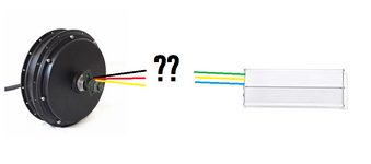
Not at all the same thing as "the red and black wire goes to the battery charger". Look, we get that you don't know what you are doing, and thats fine not everyone is experienced at this, and we're here to help. But don't cop an attitude, and be precise.

The yellow connector in the foreground is the one that goes to the battery. I'm not having a problem connecting the battery to the battery charger. I'm having a problem connecting the battery to the motor control. I can post more pictures if necessary. But like I think I said, the person who did the build taped up all the other wires basically. So in order to actually see the other wires, I'm going to have to untape everything.
If everything is taped up then you should have a ready answer as to what was once connected to what - pick the connection not taped together.

If all you have is a 2-prong and a 3-prong, then obviously that will never work and you have missed something. If your connector has a motor phase wire then its meant to connect to the motor, not the battery. ALL battery-to-controller connections, absent a proprietary system that has a data handshake of some sort (Bosch, Shimano, Specialized), have only two wires. Red and black.

Since we have zero context to do more than guess at what is being missed, more pics seem the easiest path forward. No need to disconnect anything if it was never disconnected/played with earlier.

Worth noting: Wire color conventions are only loosely followed on Far East ebike components. Red and black, we can figure that out if they are used solely together. Blue/green/yellow used alone are hall sensor wires. Everything else is up for grabs.
 

Attachments

  • citwhpstjm371.png
    citwhpstjm371.png
    83.4 KB · Views: 84
Last edited:
It happens all the time with throttles. Three wires, different colors. Cutout levers too.
 
Back