$10 DIY Smart Charger Alternative / Ver. 2.0

Try the momentary contact switch (or even just any switch operated manually) with the battery as the CD60 Input.

Funny... I thought of the same auxiliary power supply solution but kept scratching trying to think of something simpler and safer.
Do you simply mean to run a wire from the battery controller terminal
This is what I am thinking.
excuse the crude drawing as well 🙃

View attachment 115301

When you push the button you will in essence connect the charger directly to the battery. Once charging starts, release the button. It should only take a second or two.
You can test this with a regular throw switch before going through the trouble but I highly recommend using a momentary contact switch so that you don't accidently leave the switch in the wrong position on a final build. I can't guarantee that this will work, but if the battery charge port goes dead after charging stops, I don't see why not. Timing of this in the battery is the unknown...but the dOP can help here as well with any delay


What ever style it should be a Momentary Pushbutton Switch - SPST N.O. in function

let me know what you think or if something needs clarification
Thanks, but now I see why I wasn't getting it... This won't work any differently than what I already posted and isn't applicable; I'll explain :(

Upon first power up, the charger does provide power to the CD60 right from the start and the CD60 turns on. If I plug the charger/CD60 into the battery, the CD60 will function properly and charge the battery until the programmed voltage is reached.

The problem begins once the battery reaches the programmed voltage. The CD60 then shuts off power to the battery. For whatever reason (smart charger), this then causes the charger to momentarily power down for about 2-3 seconds. This charger power down occurs immediately after the CD60 has cuts power to the battery. So for 2-3 seconds the CD60 has no power and goes black.

Then after 2-3 seconds, the charger relay clicks and applies power again, the CD60 powers up and it's relay clicks to send power to the battery, the battery charge port then comes online, then the CD60 reads the battery voltage as sufficient, and the CD60 cuts the power to the battery which makes the charger cut power to the CD60... so the cycle of charger on/off/on/off, CD60 on/off/on/off, and battery voltage coming online offline on/off/on/off. This happens indefinitely because each time the CD60 gets fresh power it reboots and dOP resets from its programmed countdown from scratch (always will start over at 900 seconds or whatever it's programmed to).

If you haven't watched the video check it:

The video shows what happens when a full charge is reached without a secondary power supply for the CD60.

I will probably try and hack the CD60 so that the battery charger doesn't supply the power for the CD60 assuming I can figure out the traces on the CD60 PCB.

craigr
 
Do you simply mean to run a wire from the battery controller terminal

Thanks, but now I see why I wasn't getting it... This won't work any differently than what I already posted and isn't applicable; I'll explain :(

Upon first power up, the charger does provide power to the CD60 right from the start and the CD60 turns on. If I plug the charger/CD60 into the battery, the CD60 will function properly and charge the battery until the programmed voltage is reached.

The problem begins once the battery reaches the programmed voltage. The CD60 then shuts off power to the battery. For whatever reason (smart charger), this then causes the charger to momentarily power down for about 2-3 seconds. This charger power down occurs immediately after the CD60 has cuts power to the battery. So for 2-3 seconds the CD60 has no power and goes black.

Then after 2-3 seconds, the charger relay clicks and applies power again, the CD60 powers up and it's relay clicks to send power to the battery, the battery charge port then comes online, then the CD60 reads the battery voltage as sufficient, and the CD60 cuts the power to the battery which makes the charger cut power to the CD60... so the cycle of charger on/off/on/off, CD60 on/off/on/off, and battery voltage coming online offline on/off/on/off. This happens indefinitely because each time the CD60 gets fresh power it reboots and dOP resets from its programmed countdown from scratch (always will start over at 900 seconds or whatever it's programmed to).

If you haven't watched the video check it:

The video shows what happens when a full charge is reached without a secondary power supply for the CD60.

I will probably try and hack the CD60 so that the battery charger doesn't supply the power for the CD60 assuming I can figure out the traces on the CD60 PCB.

craigr
You may be correct....
But also see that I have the battery as the CD60 INPUT.
That might make the difference needed as I don't think it will cycle on/off at set charge voltage like the charger does. And this should solve the problem of the battery not powering the CD60 on from the start.
Again... No guarantee, but I think it worth a try.
Once the charging current is stopped by the CD60, the battery's charging port goes to zero volts. The CD60 shuts off. I tried it hoping there would be enough juice on the charging port and it didn't work :(
 
Once the charging current is stopped by the CD60, the battery's charging port goes to zero volts. The CD60 shuts off. I tried it hoping there would be enough juice on the charging port and it didn't work :(
Yeah but isn't that what we want... Once charge Volt is reached and CD60 shuts down the system stays off and does not short cycle
 
Yeah but isn't that what we want... Once charge Volt is reached and CD60 shuts down the system stays off and does not short cycle
Ah I finally get your meaning. Yeah, that probably would work than actually. The "dN" setting wouldn't have any function than, nor would "dOP" so hitting the correct voltage would be a bit more crude. But I think that what you propose would work, just without some of the fancier features of the CD60.

OK, I may give it a try and see if it works and if I can get consistent charges that way :)

Good idea!

craigr
 
One thing that I didn't put in words but is in the diagram is that you need to put a jumper on the the Negative wire across the IN-OUT terminals along with adding the switch.
Also keep in mind that the dn and dOP are meant to be used with a battery that is permanently wired to a charger as is done for solar power storage. Since you are taking this battery for a ride after a charge, they really don't have function for our hack.
Hopefully it works and just doesn't make us aware of another problem.
One possible issue may be that to change the CD60 settings may require you holding the switch closed... At which point a throw switch may be better (if you need to change them often) The down side then being if you leave it in the wrong position during a charge the CD60 will be bypassed and resulting in a full charge.

The Hack Continues....
 
This is what I am thinking.
excuse the crude drawing as well 🙃

View attachment 115301

When you push the button you will in essence connect the charger directly to the battery. Once charging starts, release the button. It should only take a second or two.
You can test this with a regular throw switch before going through the trouble but I highly recommend using a momentary contact switch so that you don't accidently leave the switch in the wrong position on a final build. I can't guarantee that this will work, but if the battery charge port goes dead after charging stops, I don't see why not. Timing of this in the battery is the unknown...but the dOP can help here as well with any delay


What ever style it should be a Momentary Pushbutton Switch - SPST N.O. in function

let me know what you think or if something needs clarification
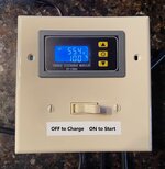
Just wanted to pop back in and say that this is working nicely. Good call man on the switch to get the process charging with the Vin and Vout reversed. I actually wound up using a two gang outlet box and a regular single pole light switch. I actually like the light switch better than a momentary switch because when I need to charge to 100% all I have to do is leave the switch in the ON position. Mine might not be as pretty as yours and probably incorporated the use of much more hot glue, but I built it with all scrap around the house and the only thing I had to buy was the CD60. I am very pleased, thank you!

IMG_2790.jpg IMG_2791.jpg IMG_2792.jpg

craigr
 
Last edited:
One thing that I didn't put in words but is in the diagram is that you need to put a jumper on the the Negative wire across the IN-OUT terminals along with adding the switch.
Also keep in mind that the dn and dOP are meant to be used with a battery that is permanently wired to a charger as is done for solar power storage. Since you are taking this battery for a ride after a charge, they really don't have function for our hack.
Hopefully it works and just doesn't make us aware of another problem.
One possible issue may be that to change the CD60 settings may require you holding the switch closed... At which point a throw switch may be better (if you need to change them often) The down side then being if you leave it in the wrong position during a charge the CD60 will be bypassed and resulting in a full charge.

The Hack Continues....
Actually, you don't need to connect the grounds. I checked before wiring and they are indeed always connected and not switched. Only the POSITIVE is switched.

craigr
 
Actually, you don't need to connect the grounds. I checked before wiring and they are indeed always connected and not switched. Only the POSITIVE is switched.

craigr
Glad you got it working as needed.
Yeah I should have ASSumed that it wasn't a 2 pole relay inside the CD60... and I was too lazy to open it up to test! 😜
Using a light switch does make it easier to mount.
I still like a momentary switch as it adds a layer of protection even when full charging as the CD60 is another shutdown on top of the charger and BMS... but perhaps overkill.
Hack on. . .
 
Last edited:
Glad you got it working as needed.
Yeah I should have ASSumed that it wasn't a 2 pole really inside the CD60... and I was too lazy to open it up to test! 😜
Using a light switch does make it easier to mount.
I still like a momentary switch as it adds a layer of protection even when full charging as the CD60 is another shutdown on top of the charger and BMS... but perhaps overkill.
Hack on. . .
That’s the beauty and fun of hacking.

Hack on!
 
Glad you got it working as needed.
Yeah I should have ASSumed that it wasn't a 2 pole relay inside the CD60... and I was too lazy to open it up to test! 😜
Using a light switch does make it easier to mount.
I still like a momentary switch as it adds a layer of protection even when full charging as the CD60 is another shutdown on top of the charger and BMS... but perhaps overkill.
Hack on. . .
If you have a second, could you please pop into my thread here:

I'm having some issues with my battery unrelated to your charger hack and I would highly appreciate your insight.

Thanks!
craigr
 
I've been experimenting with an easier way to achieve a 70% - 90% charge or a storage charge for my battery other than just timing it and I came across an inexpensive solar charge controller that I thought I might be able to adapt. In the end I am able to achieve my goal, but it didn't end up exactly as planned.

The skinny on how it works is that you wire this in between the charger and the battery and it will disconnect the two when a certain voltage is reached and/or amount of time has elapsed.

In my particular case an issue that arose was that my charger is somewhat intelligent and it varies voltage on start up as it reads battery voltage and will cycle on/off until a constant voltage is read for a few seconds. This in turn would cause the controller to cycle as well and open its contacts.
The solution I came up with was to reverse the input and output of the controller so that I connected the constant voltage of the battery to the input. Since the controller works as a simple on/off switch, this is not a problem. The downside being that there is an extra step plugging it in.
So how it works....
I plug the battery into the the controller and turn on the battery to power it up. I set my battery's Bottom End Voltage as a reference point. I used 34.5V.
I then set the Shut-off Voltage to my desired voltage... say 80% _ 50.5v
Once set these remain in memory even after unplugging and ready for future charges. The controller is easily adjusted in .1v increments from 6V to 60V
I then set the Timed Forced Off on the controller to 2 - 4 hours depending how far I ran the battery down. Then set the Delayed Restart between charges to its maximum 999 seconds ( about 16 minutes) These are also set once and are saved for future use and/or easily changed if need be.
Then I plug the charger in to electrical outlet and give it a few seconds to read battery V and start.
Once it starts I turn OFF the power switch on the battery. If not it will short cycle at the end of the charge always trying to add .1v after the 999 seconds times out and up to the Timed Forced Off.
While charging it will display either the percentage of charge it is currently at, 100% being the Shut-off Voltage set, or you can toggle to a countdown of the Forced Timed Off set. If you do not set a Forced Time Off it will display an elapsed Charge Time.


Now those with a more basic charger... you should be able to do this without swapping the input/output.

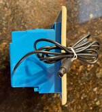
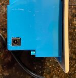
I mounted the controller in a plastic single gang electrical box and nano taped it to the top of my charger. I didn't want to hack up my charger output cable to put the controller in the line so I made an extension cable out of an old 16 gauge PC power cord and some solder XLR connectors. This also makes it easy to take the controller out of the line if need be. Careful purchasing an XLR cable for this use as in general these are used for audio signals and the conductors can be quite small.

So once set up it's a few extra seconds added to plugging things in than the charger alone and I have to say that it has been working quite well.
I will add that sometimes it is off by a tenth of a volt or two, but that's really hard to quantify as the battery voltage can fluctuate by that amount on its own. Since I usually burn through 1V or less on a typical 20 mile daily ride, only charging to 80% is not a hassle for me.


For someone with only one battery, this is a hell of a lot cheaper than the ready made alternatives while utilizing the charger you already have.
Totally missed this. WANT!!!
 
Just keep in mind that seller on Amazon has a delivery date 4-7 weeks from now; it's coming from China.

There are a lot of sellers on eBay for around $11-$12, but I paid the extra few bucks to get it quickly from a USA supplier:
eBay XY-CD60 USA Seller (link)

Sometimes I'm OK with being patient and waiting for the slow boat, but this project tickled my interest and I decided I wanted the CD60 in three days instead of who knows when.

I'd really rather have a direct power supply now instead of a charger. I could modify the charger and may just do that to keep constant voltage, but I just got the bike and charger less than three weeks ago and want to make sure everything is right before I hack away. Warranty and all.

craigr
I’m cheap. I’m an Aliexpress fan. $8.06. Those eBay sellers are usually on aliexpress and the price difference can be substantially lower.

Favourite store, cool geeky stuff.
 
Last edited:
Totally missed this. WANT!!!
It's really easy to wire up. The hard part is mounting it neatly in a 2 gang electrical box as it just barely fits and you have to be a little creative with the cover.
This works best with simple heatshrink batteries and chargers but as you can see from others it can be adapted and I used it with a hailong that had a somewhat intelligent charger
Let me know if you'd like me to put one together for you.
I have a new HS battery and am building a battery for accessories on the trike along with a solar charger basket lid. The would be cool for a plug-in for the 36v accessories. I’ve a half dozen budget chargers. $9.00 Aliexpress same ones people pay $25 for.
 
I have a new HS battery and am building a battery for accessories on the trike along with a solar charger basket lid. The would be cool for a plug-in for the 36v accessories. I’ve a half dozen budget chargers. $9.00 Aliexpress same ones people pay $25 for.
Well it is a simple Solar charge controller so it should work well. Using the same input plug as the chargers you can easily swap between the solar panels and a charger as needed.
 
Well it is a simple Solar charge controller so it should work well. Using the same input plug as the chargers you can easily swap between the solar panels and a charger as needed.
Yeah I have a decent mppt. But I love tryin* new things. I find I need to trial ideas to be able to help or support a concept. Exactly why I had so many motors. Er, have so many…

lots of fellows can’t afford or won’t spen$ the bucks for a Satiator. Your kit with meanwell PS might just be the frugal man’s Satiator.
The hack is half the fun.
I've used it for every charge since assembled and it has worked very well for me. I don't need to adjust it much as my ride time is typical and for the most part it stays set to 50.5v (80%) which for me yields up to 2 days of riding or one extended ride. I do charge every time before a ride just to keep charge time as short as possible as my ride window these days is limited and I need to squeeze it in sometimes with little advance.
 
Cool little circuit you’ve assembled. I totally agree that hacking is part of the fun. I hack other thing last for the same reason. I may use this for my 36v battery. Maybe I can use the same unit for a 36v battery and a 48v battery. Though, at the price, maybe I’ll make a separate one. I like to monitor my charging.
 
Back