seg1980
New Member
Hi,
this is the first time i bought a ebike motor and motor controller.
I'm not able to run the motor.
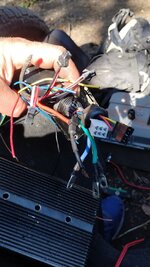
I connected three phases from the motor to the controller with same color wires
and 5 wires from motor to control with same color wires.
Now it looks that i"m missing the throttle or something to ignite the motor.
If i need a throttle can guide which one i should order?
if not can someone guide me how to start running the motor.
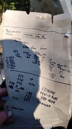
Please see the attached diagram of what i did.
Thank you

My motor has:
3 wires for motors; green, blue, yellow
5 wires which i think are Hall sensor: red, green, blue, yellow, black
My controller has:
3 wires for motor: yellow, green, blue
5 wires for hall sensor: red, green, blue, yellow, black
2 wires for battery: red, black
2 wires: orange, red : lock
2 wires: red, black: charging port
2 wires: white, orange: brake light
2 wires: white, black: low braking
1 wire: blue
1 wire: blue
2 wires: black, brown
3 wires: black, violet, pink
3 wires: black, blue, gray
this is the first time i bought a ebike motor and motor controller.
I'm not able to run the motor.
I connected three phases from the motor to the controller with same color wires
and 5 wires from motor to control with same color wires.
Now it looks that i"m missing the throttle or something to ignite the motor.
If i need a throttle can guide which one i should order?
if not can someone guide me how to start running the motor.
Please see the attached diagram of what i did.
Thank you
My motor has:
3 wires for motors; green, blue, yellow
5 wires which i think are Hall sensor: red, green, blue, yellow, black
My controller has:
3 wires for motor: yellow, green, blue
5 wires for hall sensor: red, green, blue, yellow, black
2 wires for battery: red, black
2 wires: orange, red : lock
2 wires: red, black: charging port
2 wires: white, orange: brake light
2 wires: white, black: low braking
1 wire: blue
1 wire: blue
2 wires: black, brown
3 wires: black, violet, pink
3 wires: black, blue, gray